- Joined
- Apr 1, 2011
- Messages
- 15,177
- Helped
- 2,899
- Reputation
- 5,810
- Reaction score
- 2,982
- Trophy points
- 1,393
- Location
- Minneapolis, Minnesota, USA
- Activity points
- 113,689
Hi,
can any one give me the circuit for measuring 3 phase voltage with reference to Neutral?. i tried all changes that mentioned above. but still i am not getting a stable output.
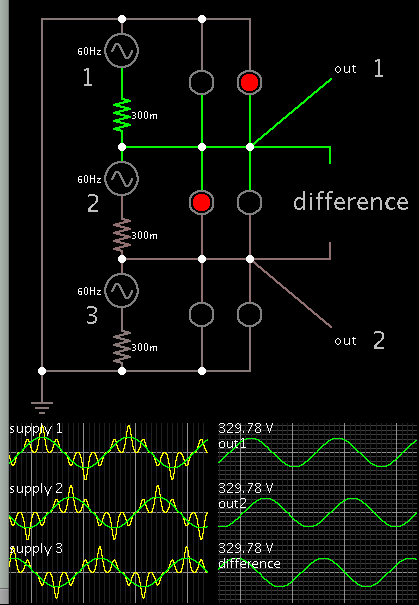
I believe this is how the 3 AC sources are arranged. (I forget if it's called the delta type or the Y-type.) To read their voltage you can choose a node between any 2 sources, and call that arbitrary ground, and get a sensible amplitude reading for those 2 sources.
However you cannot attach the third source to ground. To take the third reading you must take the difference between the other two readings. You must use their unaltered sinewaves. Subtract one from the other.
Outputs 1 & 2 are direct readings (referenced to 0V ground). To get the third reading, the simulator provides a 'scope probe' which derives the difference between Out1 & Out2. Notice the scope traces show correct waveforms. Amplitude is correct and the 3 phases are staggered 120 degrees.