Continue to Site

Welcome to EDAboard.com

Welcome to our site! EDAboard.com is an international Electronics Discussion Forum focused on EDA software, circuits, schematics, books, theory, papers, asic, pld, 8051, DSP, Network, RF, Analog Design, PCB, Service Manuals... and a whole lot more! To participate you need to register. Registration is free. Click here to register now.

Measurement of Leakage Inductance

Status
Not open for further replies.

sabu31

Advanced Member level 1
Joined
Jan 28, 2011
Messages
441
Helped
12
Reputation
24
Reaction score
13
Trophy points
1,298
Activity points
5,103
Hi all,

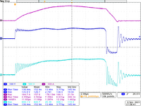
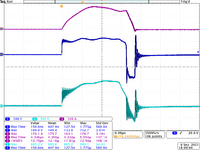
I want to measure the leakage inductance of a high voltage pulse transformer. The pulse width is 10us and frequency is 250Hz. The input voltage is to be at 500V and output at 4kV and 66A. I am using interleaved winding ( Secondary Half, Primary, Secondary Half). I am measuring leakage inductance using LCR meter by Keysight. However, at some frequencies I am getting negative inductance. what is the meaning of negative inductance shown in LCR meter. Also is this method of measuring leakage valid for low duty ratio pulse transformer.
 

Attachments

  • 3.gif
    3.gif
    9.5 KB · Views: 147
  • 2.gif
    2.gif
    9.4 KB · Views: 161
  • 1.gif
    1.gif
    9.5 KB · Views: 157

Typically you get negative inductance values if you measure above transformer self resonance frequency. I don't understand at first sight why you get negative inductance values at these low frequencies.

Inductance measurement has nothing to do with transformer operation mode, e.g. duty cycle.

What are you measuring, primary or secondary leakage? For full transformer characterization, I usually measure 4 parameters, primary and secondary inductance, other terminals both open and shorted.
Thanks FvM for the reply. I am measuring primary side leakage inductance. (secondary side is shorted). Which frequency should I measure the leakage inductance (at 250 Hz which transformer operating frequency or 100kHz which is pulse width equivalent (10us).
 

Pulse width of 10 µs corresponds to 50 kHz in my calculation. We would normally expect a mostly frequency independent leakage inductance, at least suffciently below transformer self resonance. I'm still wondering about inconsistent measurements. Looking at LCR meter accuracy diagram, you are simply outside useful range limits.

Suggests you should repeat the measurement at higher frequency, short calibration should be performed at each new frequency.
 

If you don't know enough about the effect of capacitance on the ability to measure leakage inductance properly - then you really need extra assistance with this project - the voltages are dangerous and your lack of previous experience would seem perilous to your health.
 

Hi all,
I have made a custom transformer with 4 toroidal cores stacked. The inner diameter is 8cm and outer is 10 cm with height of each core 3.5. The material of the core is amorphous iron.
I have done interleaved winding with Teflon wire
The :ayers are : Layer 1(secondary 1, 12 Turns), Layer 2( Primary, 3 Turns), Layer 3: (Secondary 2, 12 Turns).

The leakage inductance was less than 1uH under all frequencies from 10kHz to 100Khz.

However, there is substantial ringing in the voltages of secondary.
I am attaching waveform of the same
The load used is 60 ohms, Pulse duration is 13us and Frequency is 267Hz BIpolar
Channel 1 Primary Voltage
Channel 2: Secondary Voltage
Channel 3: Primary Current.

Despite the leakage being low, there is ringing. What can be used to damp the ringing.
Moreover, the current seems to be peaking, Is this core suitable for high voltage application.
 

Attachments

  • tek00056.png
    tek00056.png
    44.4 KB · Views: 135
  • tek00057.png
    tek00057.png
    55.8 KB · Views: 135

Negative inductance is merely capacitance. The spectral density of a 10us pulse at 250 pps are sine/cost phases of all the harmonics from 250 Hz declining to a null at 100kHz =1/PW then lower repeating with harmonics with a null at 200kHz etc . The question I have is what is the risetime and PW50 of the output.

- your mutual coupling and leakage inductive impedance drops at lower frequencies and becomes harder to measure for this type of pulse transformer. Ideally you would use a network analyzer on the input and output and match both sides with their operational impedances but in this it would dampen the result so you would drive it at some level from a high impedance , your flyback open circuit then design a 60 ohm 20 or more dB pad on the output due to step up ratio to protect the input. Then measure the gain phase response. You could also use an FM sig gen and a scope with a sawtooth driving FM from the X axis analog sawtooth output of an analog scope.
 

@ Klaus - no diodes by the look of it,

the capacitance is easily measured at a few 100 Hz or less, no need for a VNA for that, what would be instructive is a look at the Z for the shorted Tx - I note that the Ridley box does this very well from 1Hz to 10MHz with little error.

One can easily see from the waveforms that excess capacitance is the cause of all the ringing - there are ways to wind to reduce this - for pulse applications a very in-depth knowledge of Tx design and construction is necessary to get clean pulses with sharp rise times ( low leakage ) - esp at the several kV you seem to be requiring ...

We have designed planars with leakages < 1nH for this purpose - the wiring to and from the Tx dominating the stray L - hence the driver must be very close to the Tx too if you want best results.
 

    sabu31

    Points: 2
    Helpful Answer Positive Rating
Negative inductance is merely capacitance.
According to instrument accuracy curves, negative inductance measurement in the post #1 results is merely an artefact. Apparently a more or less plausible leakage inductance of 1 µH has been identified in later measurements. Unfortunately you didn't tell if it's measured on the primary or secondary side.

1uH and 5 MHz ringing frequency makes 1 nF.
 

to be fair / realistic, there is no way the measured Llk is that low for the simple wdg construction described, it appears the C is affecting the L meas, as it is based on Z measured .... this is proven by the negative value at the rather low meas freq of 1 kHz, indicating the SRF is very low indeed ....

btw, the signal level is very low too ...
 
Last edited:

It's almost impossible to achieve kHz range SRF with 24 turns. Thus the negative inductance numbers in post #1 are just implausible.

According to Agilent E4980A specification (the instrument apparently used in post #1), you achieve about 10 % accuracy for 1 µH measurement at 1 kHz. Correct calibration is however required. That's possibly the reason why we got the wrong numbers.

1631261055826.png
 

    sabu31

    Points: 2
    Helpful Answer Positive Rating
According to instrument accuracy curves, negative inductance measurement in the post #1 results is merely an artefact. Apparently a more or less plausible leakage inductance of 1 µH has been identified in later measurements. Unfortunately you didn't tell if it's measured on the primary or secondary side.

1uH and 5 MHz ringing frequency makes 1 nF.
Thanks FVM for the reply. I am measuring at primary with the secondary shorted for measuring through LCR meter
--- Updated ---

Hi,

What diode did you use?
(I think about big trr.)

Klaus
I have used two IGBT modules to SKM 200GB 12E4. two generate Bipolar Square wave. This Bridge is connected to Step Transformer.
--- Updated ---

@ Klaus - no diodes by the look of it,

the capacitance is easily measured at a few 100 Hz or less, no need for a VNA for that, what would be instructive is a look at the Z for the shorted Tx - I note that the Ridley box does this very well from 1Hz to 10MHz with little error.

One can easily see from the waveforms that excess capacitance is the cause of all the ringing - there are ways to wind to reduce this - for pulse applications a very in-depth knowledge of Tx design and construction is necessary to get clean pulses with sharp rise times ( low leakage ) - esp at the several kV you seem to be requiring ...

We have designed planars with leakages < 1nH for this purpose - the wiring to and from the Tx dominating the stray L - hence the driver must be very close to the Tx too if you want best results.
Thanks Easy Peasy for the reply. Are toroidals or U Cores better suited for this. I have tested with toroid as it has inherently lower leakage compared to U core. Also I am getting better magnetising inductance (390uH at 100kHz) with Toroidal Core. With U core I am getting very low magnetising inductance of 50uH at 100Khz. What winding structure is good for toroid. Also can you refer me to the type of transformer core shape (planar) and design materials for the same.
 
Last edited:

I may have assumed you driver incorrectly but Coss of each polarity will interact with Lp and transformed secondary. Matching impedances with conjugated reduces efficiency to 50% may not be desirable. What are your expectations? Specs?? Rce of IGBT, DCR, Lp, Q Overshoot resonance, decay time? Coupling capacitance? Efficiency? It is rare to find a power pulse magnetic over several decades of BW. Bpk/Bsat ratio ? I can model this if you give all the parameters for determining optimization.
 
Last edited:

Coss of each polarity will interact with Lp and transformed secondary.
... only after the current has fallen to zero - during the power pulse & after switch off - there is significant current in play causing the source Z to be low - after the current drops to near zero, only, will there be ringing according to the parasitics - and then again - only if the bottom IGBT devices are left off - they may be ON to limit this effect ( or the Tx pri may be shorted some other way ).
--- Updated ---

Also - there is not enough information about the load to make intelligent comment.
 
Last edited:

The trouble is - the load is unknown, so measuring the slopes is all assumption.
Yes the equivalent model is an assumption with just a load resistor at 1nH/mm and the layout, driver impedance and load capacitance are unknown affecting the results.

I presume the load is the easy peasiest part, with ESL much lower than Lp, Ls so we can gather the equivalent reactance at various currents and impedance of switching resonant frequencies.

I just did a rough cut to show this transformer is not linear over 3 f decades, and 1 decade of current, as I expected. An air gap increases leakage L, but makes it more linear, an important tradeoff. Normally for me I would expect high voltage , high BW transformers to be mica tape insulated with very fine Litz wire (AWG48 bundled to desired AWG) using exotic high Bmax cores with a very small air gap., with an epoxy pour after testing and GaN switches or Mistubishi IGBT's (7th or 8th generation ?)

If you can model it and can imagine it , you can simulate it.
 
Last edited:

An air gap does not increase Llk, this is a known physics result.

Pulse Tx design for 10kW<Pdesired< 100kW are very different to low power pulse Tx's
 

Status
Not open for further replies.

Part and Inventory Search

Welcome to EDABoard.com

Sponsor

Back
Top