Continue to Site

Welcome to EDAboard.com

Welcome to our site! EDAboard.com is an international Electronics Discussion Forum focused on EDA software, circuits, schematics, books, theory, papers, asic, pld, 8051, DSP, Network, RF, Analog Design, PCB, Service Manuals... and a whole lot more! To participate you need to register. Registration is free. Click here to register now.

Measurement of differential output impedance

Status
Not open for further replies.

m100191ec

Newbie level 4
Joined
Sep 9, 2011
Messages
5
Helped
0
Reputation
0
Reaction score
0
Trophy points
1,281
Location
INDIA
Activity points
1,317
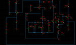
I have designed balun-LNA using parallel combination of CS and CG stage. My circuit has differential output and single ended input. I matched the input for 50ohms since it is single ended. But my doubt is how to match the differential output for 100ohms.
For output impedance matching, i have separately matched the output for 50ohms assuming virtual ground.(for both outputs of CS and CG buffer stages). After matching i lifted the virtual ground and the output capacitors will come in series. I replaced them with single capacitor ( series combination). I haved used capacitors for matching purpose at the output of buffer stages.

With this setup, i measured S22 by keeping port in between the terminals.
I want to know whether my way of thinking is correct?

I want to know how to measure the gain imbalance of the differential ciruits?

Any help would be appreciated
 

Could you post the figure?
If you are testing on PCB, why not use a balun followed by the NA.
 

You can use mixed mode s-parameters to have a full linear characterization of the LNA.
There is a lot of literature about mixed mode S-parameters (google it), I'm giving you just a glance about them:

Your device is a 3 port device ( ports are: in, outp, outn) that can be represented as a 3 port device (ports are: in,out_diff, out_comm) without any loss of information.

You need first to measure the S3P matrix (in, outp and outn). If you have a 4 port VNA this is straightforward, if you don't have it you can measure the 2 S2P files (in, outp, with outn terminated with 50 Ohm) and (in, outn, with outp terminated with 50 ohm). Then you have to combine the two 2X2 matrix to obtain a 3X3 matrix.
Now you've got the S3P file.

Apply mixed mode transform and obtain a new S3P file in which you'll have, for example Sd1 as the gain of the LNA, Sc1 as the common mode rejection, Sdd from which you can calculate the differential output impedance and so on. Use a simulator like Agilent ADS or a similar one, or matlab, or mathcad, or whatever you prefer, you just need to know the equations behind that.

Be aware that you need to measure the S-parameters with input level well below the P1dB (at least 10 dB below) of the LNA, remember you need to be in the linear region.

I hope it can help.

Mazz
 

Thanks Mazz, for responding to my question.
Ya i agree that mixed mode parameters is one of the options to calculate differential impedance. But is there any means to calculate differential impedance directly without using mixed mode parameters.I have have calculated the output impedance by placing the port in between the two output terminals.I am uploading the circuit. correct me if i am wrong.
 

Attachments

  • circuit.PNG
    circuit.PNG
    38.6 KB · Views: 85

Status
Not open for further replies.

Part and Inventory Search

Welcome to EDABoard.com

Sponsor

Back
Top