Continue to Site

Welcome to EDAboard.com

Welcome to our site! EDAboard.com is an international Electronics Discussion Forum focused on EDA software, circuits, schematics, books, theory, papers, asic, pld, 8051, DSP, Network, RF, Analog Design, PCB, Service Manuals... and a whole lot more! To participate you need to register. Registration is free. Click here to register now.

[SOLVED] MCU clock cycle = crystal frequency used ?

Status
Not open for further replies.

Onigece

Member level 1
Joined
Nov 2, 2011
Messages
34
Helped
3
Reputation
6
Reaction score
3
Trophy points
1,288
Activity points
1,501
MCU clock cycle = crystal frequency ?

How is the 'clock cycle' of PIC MCU related to the 'crystal' oscillator connected between pins OSC1 and OSC2?
 
Last edited:

PIC12, PIC16, PIC17 and PIC18 series divide the external (crystal) clock into four phases, each used internally to operate the logic elements. This means the internal 'clock cycle' Tcy or instruction speed is 1/4 of the external oscillator speed. For example a 4MHz crystal would produce one million clock cycles.

On some PIC24, PIC 30 and PIC33 series the external clock is used as the 'clock cycle' generator.

Some PICs also have PLL frequency multipliers inside them which allow the internal clock cycles to be faster than the external clock.

Brian.
 
If I am connecting a 20MHz crystal between the pins OSC1 and OSC2 of PIC12/PIC18, which is correct?

a.) Instruction cycle = 20MHz/4 = 5.0MHz (0.2us)
b.) Instruction cycle = 20MHz/8 = 2.5MHz (0.4us)
c.) None of the above. (why)
 

I think the answer you are looking for is 'a' but it assumes the PIC18 does not have an internal PLL clock multiplier - many do. For example I use PIC18F36J11 devices with 16MHz crystals but multiply it up to 48MHz with the internal PLL.

Brian.
 
fig0-27.gif

This image from Chapter 1: World of Microcontrollers - Book: PIC Microcontrollers - Programming in C confuses me. Why the crystal frequency (20MHz) is divided by 4? Shouldn't the crystal frequency (20MHz) be directly applied to the processor?
 
Last edited:

Microchip are honest about the operating speed of their processors, some manufacturers only quote the maximum crystal frequency.

The 'Tcy' cycle time is 1/4 of the clock frequency because each instruction needs several steps to complete. It isn't just divided by 4 then used, each of the clock cycles actually does something inside the PIC but it takes four of them to operate the hardware to complete one instruction. One popular processor which clocks at high speed takes 178 clock cycles to complete some instructions so execution is actually much slower than you would expect. All PICs can complete one instruction in only four clock cycles with the exception of a few conditional branches/jumps which take 8 cycles.

Brian.
 
Does PIC uses pipelining? If it does, then even if an instruction needs 4 clock cycle for execution the effective clock cycle for each instruction is 1.
I'll elaborate more on what I mean/think: If PIC uses pipelining, the first instruction would need 4 clock cycle to be executed. However succeeding instructions would only need 1 clock for execution. Therefore I can say that this PIC has single cycle instruction, right? And because it only needs single clock for execution, there should be no need to show that 'divided by 4'. Am I right?
 

Am I right?
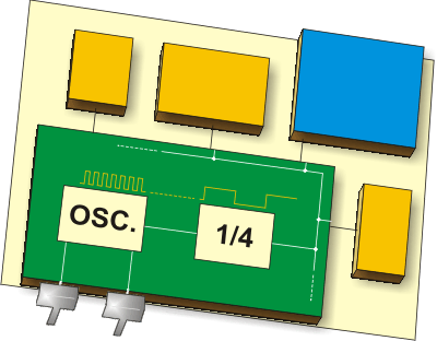
No. As has already been stated, the small PICs divide the crystal frequency by 4 and that is the instruction cycle clock. On each of the four phases generated by the division, specific events are happening within the processor. If you do a simple test you will easily be able to confirm this - run a PIC with a clock of your choice and toggle an I/O line and look at it on an oscilloscope.

Keith
 
I don't have oscilloscope at home, is simulation just ok? I need to download one if necessary.

@Betwixt and keith1200rs > By the way do you think that the '1/4' in the image means 'instruction frequency' or there is really an internal circuit that divides the crystal oscillator frequency (i.e. 20MHz) by 4 which is used to clock some internal components (i.e. TMR0)?
 
Last edited:

All PICs are pipelined but the 'pipe' is only filled once every four clock cycles. If you look in the data sheets under "Instruction Flow/Pipelining" it will show a diagram whch explains the sequence of events. Note that the time scale is in Tcy not in clock cycles. Basically, the next instruction in memory is read while the current one is executing unless the instruction may cause a jump to a new (and unknown until execution) address.

Brian.
 
Status
Not open for further replies.

Similar threads

Part and Inventory Search

Welcome to EDABoard.com

Sponsor

Back
Top