Continue to Site

Welcome to EDAboard.com

Welcome to our site! EDAboard.com is an international Electronics Discussion Forum focused on EDA software, circuits, schematics, books, theory, papers, asic, pld, 8051, DSP, Network, RF, Analog Design, PCB, Service Manuals... and a whole lot more! To participate you need to register. Registration is free. Click here to register now.

MCP6001 Opamp on single supply...can it drive down to ground?

Status
Not open for further replies.
T

treez

Guest
Hello,
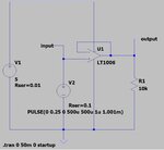
If the MCP6001 opamp is set up as a buffer, and receives a triangular wave of peak 0.25V and frequency 1kHz as an input (as in attached green waveform), can it reproduce the waveform at its output?.....or will it not be able to get right down to ground?, as is the case with the LT1006 as attached (LTspice sim and schem)

MCP6001 opamp datasheet
https://ww1.microchip.com/downloads...1U-2-4-1-MHz-Low-Power-Op-Amp-DS20001733L.pdf
 

Attachments

  • input and output waveforms.jpg
    input and output waveforms.jpg
    102.4 KB · Views: 183
  • Opamp near ground.jpg
    Opamp near ground.jpg
    77.6 KB · Views: 181
  • Opamp Near ground.txt
    1.2 KB · Views: 96

The datasheet for the MCP6001 says that the output goes down to a maximum of 25mV.
 
  • Like
Reactions: treez

    T

    Points: 2
    Helpful Answer Positive Rating

    Easy peasy

    Points: 2
    Helpful Answer Positive Rating
Often you can supplement the low side drive
with a shunt resistor. But in any case you have
to accommodate the load impedance-to-
some-higher-voltage (voltage divider).

The 25mV spec value probably pertains to
a spec load condition and contains some
"sandbagging" for test yield. But face it, with
no negative voltage to use, you can never
get to 0.000000V unless your load is infiniteZ
and your op amp piece has no internal
leakage from the high side onto the low side
drive device.

It's never a good idea to depend on a perfect
ground anyway. A "virtual ground" reference
that sits between the rails you've got, would
offer more margin against various nonidealities.
 
  • Like
Reactions: treez

    T

    Points: 2
    Helpful Answer Positive Rating
The opamp output is class-AB to avoid crossover distortion therefore it has some current through its output transistors when it is trying to drive the output as low as is possible. This current through its output causes the 25mV max low and minus 25mS from the positive supply for its minimum output high voltage.
 
  • Like
Reactions: treez

    T

    Points: 2
    Helpful Answer Positive Rating
Hi,

No Opamp can drive to it's rails when there is current flow.
Just close to it. How close tells the datasheet.

Klaus
 
  • Like
Reactions: treez

    T

    Points: 2
    Helpful Answer Positive Rating
LM358 / 324 can get to within 5mV of gnd for the A class device and 100 ohm to gnd on the o/p
 
Hi,

When you show your whole circuit / whole idea, then we will find a way...
Either with a bootstrap circuit, or offset ..or ...

Klaus
 
Apparently nobody has read the data sheet completely.

The 25 mV spec is for a load connected to mid suppy.
4.2 Rail-to-Rail Output
The output voltage range of the MCP6001/2/4 op amps is VDD – 25 mV (minimum), and VSS + 25 mV (maximum) when RL = 10 k is connected to VDD/2 and VDD = 5.5V. Refer to Figure 2-14 for more information.

Figure 2-14 suggests that the output swings to zero (below 1 mV) with pull-down load. The LTspice macro model probably doesn't reflect the behavior in this point. Instead of inviting further guesses, you may want to check with the real chip.
 
Status
Not open for further replies.

Part and Inventory Search

Welcome to EDABoard.com

Sponsor

Back
Top