karanbanthia
Junior Member level 1
Hi All,
I am using MC34063A in step down configuration, but it switches OFF during every cycle. Following are the parameters for which it is designed:
Vin - 9 to 12V
Vout - 5V
I max - 0.3A
Rsc - 0.36 ohms
L - 47uH 1.6A
Ct - 270pf
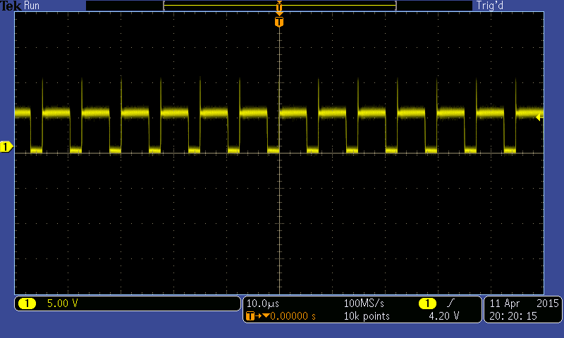
I have tried reducing the current limit resistor (Rsc), but it didn't help, the current is well below the designed limit. I have attached an oscilloscope image showing output voltage ripple on channel 1 and switching transistor emitter (pin-2) voltage on channel 2. Note that the switching stops every cycle which is unwanted and causing a low frequency ripple on the supply voltage and rest of the circuit.
Kindly help!

I am using MC34063A in step down configuration, but it switches OFF during every cycle. Following are the parameters for which it is designed:
Vin - 9 to 12V
Vout - 5V
I max - 0.3A
Rsc - 0.36 ohms
L - 47uH 1.6A
Ct - 270pf
I have tried reducing the current limit resistor (Rsc), but it didn't help, the current is well below the designed limit. I have attached an oscilloscope image showing output voltage ripple on channel 1 and switching transistor emitter (pin-2) voltage on channel 2. Note that the switching stops every cycle which is unwanted and causing a low frequency ripple on the supply voltage and rest of the circuit.
Kindly help!