rcgalicha
Newbie level 4
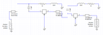
Hi all. I know this will be a stupid question but I'm really confused. Attached is a picture of my amplifier design.
Transistor used is ATF 36077 and topology is cascaded, reactively terminated amplifier.
The microstrip transmission lines are supposed to be for matching purposes however I don't know what value of impedance to put on the transmission line calculator. I just put in 50 ohms for the impedance for some of the transmission lines and frequency is 11.25 GHz. Please help. I need to know how to match this circuit properly.