sina_always_stuck
Newbie level 3
Hi,
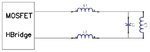
The following circuit is the the very basic form of an Hbridge inverter driving a parallel LC tank at its resonance frequency 200khz. The Inductors L1 and L2 are put in series between the square wave output of the Hbridge and the parallel resonance LC tank now I have the following three questions about L1 and L2:
1.How they change the shape of hbridge output square waves(what driving signal shape LC tank sees)?
2.How they change amplitute of hbridge output square waves(what amplitude the LC tank sees)?
3.How they change phase of the hbridge output square waves(what phase difference they introduce between hbridge output square waves and the LC tank input driving waves)?
I want to first understand the concepts and then learn the related equetions.
Any body able and willing to answer the questions and I will discuss it in more detail.
thank you in advance