Continue to Site

Welcome to EDAboard.com

Welcome to our site! EDAboard.com is an international Electronics Discussion Forum focused on EDA software, circuits, schematics, books, theory, papers, asic, pld, 8051, DSP, Network, RF, Analog Design, PCB, Service Manuals... and a whole lot more! To participate you need to register. Registration is free. Click here to register now.

Make Output voltage constant using some circuitry

Status
Not open for further replies.

hamid159

Full Member level 3
Joined
Aug 25, 2013
Messages
176
Helped
14
Reputation
28
Reaction score
14
Trophy points
1,298
Location
Lahore
Activity points
2,488
Hi guyz,
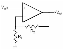
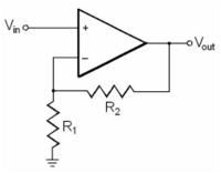
Hope you will be all fine. I am making signal generator using stellaris launchpad TM4C123g. I am getting Sine wave, saw tooth and square wave at the output. But the problem is that when i increase the frequency, output voltage (across capacitor) decreases in case of sine and saw tooth wave due to decrease in reactance of capacitor.I want to have same amplitue at output. For this, I thought a non-inverting amplifier circuit that will depend on the frequency. As frequency increases, its voltage gain will increase. So, in following figure, i replaced R1 with a capacitor and selected the combination of R2 and C such that it has 2 gain at 10KHz. But i am not getting sine wave at all at the output (while input is sine wave).
PS: Amplitude of input to the op amp is small (to avoid the saturation).
Biasing of op amp is enough to have output without clipping.

Is this circuit is valid for this purpose? or another circuit could do the job?
Thanks in advance :)

 
Last edited:

I am getting Sine wave, saw tooth and square wave at the output. But the problem is that when i increase the frequency, output voltage (across capacitor) decreases in case of sine and saw tooth wave due to decrease in reactance of capacitor.

Which "output", which "capacitor"? Please describe your circuit completely! Are you generating an analog output signal through PWM?

An OP can be also saturated in output current limiting, not only voltage limiting. That's most likely what happens in your OP circuit. You would want to tell the OP details as well.
 

Actually i am using PWM to generate sine wave and saw tooth voltage which is then passed through RC series circuit. The output is across capacitor.
Sorry, i forgot to tell the op amp details.. It is LM324 chip.
 

O.K. PWM with a RC filter. Which values? PWM frequency? Where do you connect the OP? How's the OP output loaded?

LM324 is probably too slow for the application (has bandwidth and slew rate limitations). To extend PWM DAC frequency range, you'll preferably use a higher order low-pass filter with well considered cut-off frequency. There must be of course a sufficient distance between highest signal and pwm frequency.
 

The very old and very slow LM324 is the first problem. It also produces crossover distortion that you will see and hear on the sinewave and triangle wave.
The second problem is probably the RC filter that smoothes the PWM but also cuts high frequencies.
The third problem: You made a high frequency boost circuit that has infinite gain (and noise) at high frequencies. Tge capacitor to ground that replaced R1 should have a series resistor to limit the maximum gain.
 

Thanks to all for your valuable suggestions.
FvM and crutschow, i am generating variable frequency (100Hz to 10KHz) sine and sawtooth wave. In RC filter, i have R = 5.6K and C = 300nF. Outpu of op amp is unloaded. The voltage across capacitor is the input to the op amp (+ve ternminal).
I have a variable frequency. how can i choose the cut-off frequency?

Auioguru, do you suggest any other op amp that fits my conditions? At RC filter, sine wave is almost sine wave. below is the picture of sine wave that i am getting at RC filter (across capacitor).


- - - Updated - - -

Moreover i am taking 32 samples for one cycle of sine wave.
 

EDIT:
Without your detailed schematic we are just guessing.
If the input of the opamp has a 5.6k series resistor feeding a 300nF capacitor to ground as a lowpass filter then it has a cutoff frequency of 95Hz. So 95Hz is down -3dB and 191Hz is down 6dB (half the level of very low frequencies) and 381Hz is down -12db (1/4 the level of very low frequencies) etc.
Why such a simple filter and why is its cutoff frequency so low that it cuts all the frequencies you want??
 

If the sinewave is at 100Hz and there are 32 samples then the PWM frequency is 3200Hz.
If the sinewave is at 10kHz and there are 32 samples then the PWM frequency is 320kHz.

The filter could be a switched capacitor lowpass filter IC with many orders so it filters very well. Its clock is 50 times or 100 times the sinewave frequency and can be from the micro.
 

The sampling rate and PWM frequency aren't necessarily the same.
 

Please tell us the PWM frequency so we can provide an informed answer to your question.
Otherwise we are just guessing.
 

Yes. Audioguru is right.

"If the sinewave is at 100Hz and there are 32 samples then the PWM frequency is 3200Hz.
If the sinewave is at 10kHz and there are 32 samples then the PWM frequency is 320kHz."

So, PWM frequency is varying between 3200Hz and 320KHz. That's why at lower sinewave frequencies, i do not get exactly same sine wave rather has sharp slope between adjacent samples due to greater time for the capacitor to discharge (which can be seen in above image (post #7)).
 
Last edited:

A switched-capacitor lowpass filter IC has its cutoff frequency set by its clock frequency that can be 100 times its cutoff frequency. The micro can make its clock track its sinewave frequency.

Your filter is extremely simple with only one RC. Therefore it filters with a gradual slope that cuts away some of what you want to keep and does not completely filter away what you do not want to keep. A switched capacitor filter IC can have many RCs and is active so it has a very sharp cutoff that saves what you want and cuts away the harmonics that you want cut away.
 

I agree that switched capacitor filter is a straightforward solution for a filter with scalable cut-off frequency.

But I think, the additional effort questions the meaningfulness of the presented signal generation solution as a whole. It rather shows that you'll better follow a different approach, constant sample rate and fixed output filter, as industry standard digital signal generators do.

The most annoying point is that you hardly have a suitable SC filter in your drawer or can it make easily from available standard components, at least if it's higher order. I also guess that the OP don't has access to SC filters in his region.

If you want to keep the variable pwm frequency idea though, e.g. to get better resolution at lower signal frequencies, you can use a filter bank with 2 to 4 fixed cut-off frequencies. As mentioned above, you'll surely want a higher filter order to get constant output magnitude versus signal frequency and good attenuation of pwm residuals. I won't start below third order butterworth filter.
 

Thanks.
Hi FvM, it is what i am doing here, constant sampling rate.but variable PWM frequency (which i think is necessary as well in industry standard signal generators ). For simple third or forth or fifth butterworth filter, what cut-off frequency should i choose as my sine frequency will not be constant?
Which filter either switched capacitor or simple will be better for over all performance?
If i choose either switched capacitor or simple filter but with high order let say 5th order, signal will get attenuated at each stage.
As Audioguru said, i can choose my own cut-off frequency in switched capacitor filter by mean of clock. So, for 100Hz sine wave i would generate 100Hz (cut-off) clock for switched capacitor filter and i would be getting frequency components below 100Hz which again is not a single component of 100Hz. is it true?
 

Here is the frequency response curve of a Maxim switched capacitor filter IC. It has an 8th order Butterworth lowpass filter. It attenuates the very strong 3rd harmonic of a squarewave pretty well when its cutoff frequency is up to double the wanted frequency.
You probably need a simple high frequency anti-aliasing filter at its input and another simple high frequency filter at its output to attenuate the low level clock leakage signal.
 

Attachments

  • switched capacitor filter IC.png
    switched capacitor filter IC.png
    21.4 KB · Views: 78

what i am doing here, constant sampling rate.but variable PWM frequency (which i think is necessary as well in industry standard signal generators ).

I'm not sure what you consider an industry standard signal generator. I was referring to so called arbitrary function generators. As an example, see the Agilent 33220. It can generate a sine waveform up to 20 MHz, using a 50 MS/s 14 Bit DAC. Respectively it uses a fixed low-pass filter to interpolate the DAC output to a continuous waveform. The sine waveform is generated by DDS method, so a new sample is calculated every 20 ns, independent of the sine frequency. There's no need for a variable filter in this generator design. For sine waveforms, a steep 9th order elliptical with a cut-off frequency slightly below the nyquist rate is used, for arbitrary waveforms a smooth 7th order Bessel filter.
 

So, i think i should probably go with the switched capacitor filter because all i have in one single chip and it has high attenuation above cut-off frequency. Moreover the design would be simple.
You probably need a simple high frequency anti-aliasing filter at its input and another simple high frequency filter at its output to attenuate the low level clock leakage signal.

Why do i need anti-aliasing filter? This chip is attenuating high frequency components.
And Why high frequency filter at output? after passing through filter, signal would have fully attenuated (more than enough) high frequency components.
 

Status
Not open for further replies.

Similar threads

Part and Inventory Search

Welcome to EDABoard.com

Sponsor

Back
Top