Continue to Site

Welcome to EDAboard.com

Welcome to our site! EDAboard.com is an international Electronics Discussion Forum focused on EDA software, circuits, schematics, books, theory, papers, asic, pld, 8051, DSP, Network, RF, Analog Design, PCB, Service Manuals... and a whole lot more! To participate you need to register. Registration is free. Click here to register now.

[SOLVED] LTspice DC issue

Status
Not open for further replies.

Mustaine

Member level 1
Joined
Mar 27, 2021
Messages
32
Helped
0
Reputation
0
Reaction score
0
Trophy points
6
Activity points
214
Hello friends,
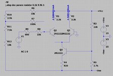
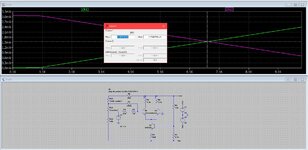
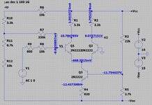
In the circuit below i am trying to equal the emitter currents of differential amplifier by changing the resistors R10 and R11 (both constitute a potentiometer) but i find different resistance values between sweeping the resistance and directly putting the exact 2.5k and 7.5k ohms.
Can you guess or tell the difference why is it like that. Do i do something wrong.
Which resistance values do you think right 2.5k, 7.5k or 3.3k, 6.7k ?
thank you in advance.
 

Attachments

  • pic2.JPG
    pic2.JPG
    161.1 KB · Views: 113
  • pic1.JPG
    pic1.JPG
    294.5 KB · Views: 119

What's the objective of this experiment?You are trying to compensate asymmetric base resistors of the differential pair by an offset voltage. Why not making the effective base resistance of both transistors equal?
 

Where on earth will you find identical old 2N2222 transistors?
The currents in the differential transistors will also change when a load is added to one of them.
 

Where on earth will you find identical old 2N2222 transistors?
The currents in the differential transistors will also change when a load is added to one of them.
What's the objective of this experiment?You are trying to compensate asymmetric base resistors of the differential pair by an offset voltage. Why not making the effective base resistance of both transistors equal?

thanks for your replies the circuit is examined for the wide band amplifier (for school).
Actually my question was about the ltspice simulation.
Did you understand why simulation does not give me the 2.5 and the 7.5 resistance values in the first place?
 

Hi,

Honestly I don't completely understand what you want to achieve.

You say you change both values R10 and R11.
Is this always true: R10 + R11 = 10k?

Do you need AC1 for this test? If not .... just to be sure it has no bad influence ... replace it by a GND symbol.

Klaus
 

Hi,

Honestly I don't completely understand what you want to achieve.

You say you change both values R10 and R11.
Is this always true: R10 + R11 = 10k?

Do you need AC1 for this test? If not .... just to be sure it has no bad influence ... replace it by a GND symbol.

Klaus
thanks for the reply.
What i want to do is to make sure that both of the collector currents of differential amplifiers are equal to do that i need to change R10 and R11 resistors(potentiometer).However both of the images that i have uploaded at seems like okay in both situation the circuit has equal collector currents but no!!
at the pic1 seems 6.7k and 3.3k okay but when i add these resistors on the circuit i gives me absolutely different currents like in the below image.
after i realize that error i tried random resistance values and found that correct resistors are 2.5k and 7.5k .
so i wonder why it is like that did i do something wrong??
 

Attachments

  • pic3.JPG
    pic3.JPG
    156.4 KB · Views: 91

Problem is your .step command that has only three points (1 per decade). It creates the imagination of a linear charactistic which isn't real. Repeat with reasonable number of points.
 

    Mustaine

    Points: 2
    Helpful Answer Positive Rating
Problem is your .step command that has only three points (1 per decade). It creates the imagination of a linear charactistic which isn't real. Repeat with reasonable number of points.
wow why i never tried that i dont know but you really helped me thanks
 

Status
Not open for further replies.

Similar threads

Part and Inventory Search

Welcome to EDABoard.com

Sponsor

Back
Top