Continue to Site

Welcome to EDAboard.com

Welcome to our site! EDAboard.com is an international Electronics Discussion Forum focused on EDA software, circuits, schematics, books, theory, papers, asic, pld, 8051, DSP, Network, RF, Analog Design, PCB, Service Manuals... and a whole lot more! To participate you need to register. Registration is free. Click here to register now.

LTC4020 battery charger charging current unstable

Status
Not open for further replies.

hoi

Newbie level 5
Joined
Oct 1, 2021
Messages
8
Helped
0
Reputation
0
Reaction score
0
Trophy points
1
Activity points
127
Hi everyone,

I am making a battery charger with LTC4020 to charge 12S li-lon battery but having problems for months and still could not fix it.

Input 24V
output 43V 2.5A charge current
battery voltage range 24V-43V (cell voltage 2V - 3.6V)

schematic setting
Maximum input current 10A
charging current 2.5A
battery float voltage 42.86V
Maximum output voltage 43.7V
Precharge voltage 28V

Problem
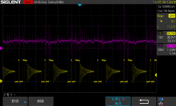
The charge current is lower than expected value, it should be maximum 2.5A but I could only get 0.5-1A charging current. And the waveform is strange.

I tried to tuned Vc and ITH value for weeks, it change a little bit with different value but could not solve the problem.

I tried to contact local FAE but did not get any useful information, tried to post the question in AnalogDevices forum but no one reply. Google searching LTC4020 and it seems some people here are using this chip so I think maybe I could get help from here. I would really appreciate if anyone could help.

The attachment is schematic, waveform of SW2 and charge current.

Thanks
 

Attachments

  • Charger_new.pdf
    615.1 KB · Views: 170
  • SDS00064.png
    SDS00064.png
    45 KB · Views: 170
Last edited:

Using differential full bridge diagonal Gate drive probe measurements (Ch1-Ch2)Math on DSO if probes are flatline calibrated on same noisy signal then they should look better than these which I degraded with 5 nH ESL between Bridge and output array caps. Then ideal next below when removed.

1633309674632.png

--- Updated ---

5nH Parasitic ESL removed ~ 0.8nH/mm
Less is wide, more if skinny

Clean Gate signals due to Miller capacitance feedback from Drain to Load Cap ESL removed.

1633310827042.png
 
Last edited:

Thanks so much for the simulation, it is very helpful!

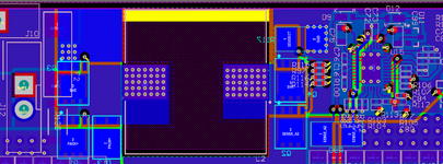
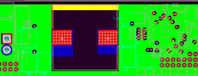
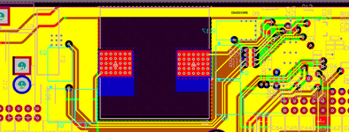
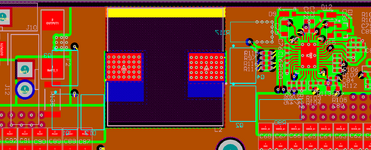
In fact, it is my second design, the first design was 4 layer with no ground around the inductor which should be less parasitic capacitance and inductance, but behaved the same.

And the inductor demo board used is 5.6u 0.003Ohm, isn't that more sensitive to parasitic capacitance and inductance?

However I also think it is parasitic problem causing the problem. Since if I add 100 Ohm to 4 MOSFET gate, it actually could achieve 2.5A charge current sometimes, but the MOSFET become very hot in few seconds.
 

Attachments

  • bottom.png
    bottom.png
    165.8 KB · Views: 83
  • layer2.png
    layer2.png
    109.8 KB · Views: 83
  • layer3.png
    layer3.png
    158.2 KB · Views: 85
  • top.png
    top.png
    165.3 KB · Views: 87

I have not had to do this before either, as I've been retired for 15 yrs, but I installed LTspice and voila.

I prefer modelling parasitics in Falstad in realtime for a simple block.

If you can design the best switching inductor thermal radiator without insulating the pads with the body and coupling stray capacitance to ground yet having guard rings to snubber resistors then the current and EMI leakage vs thermal pad radiation size can be expanded. It's a tough thermo-parasitic tradeoff design. Look at how MOBO's do it. for the 100W CPU and RAM.

1633315601946.png


We used to have notepads with these graphs for designing filters and SMPS to design resonant and anti resonant designs. You can find the PDF on the web. which zooms better than this image.

Good work and good luck. Get some experience following MOBO SMPS designs. and kW DCDC converters. My time is done on this thread.
 

Thanks so much! You help a lot.

It seems that the problem could be solved by change the low side Rsense capacitor. I changed it to 4.7uF and it seems work fine now. Detail test later
Refer to datasheet, CSENSB ~ 1nS/RSENSEB. All typical application and the demo board use 0.033uF, but it is too small if refer to the equation, and 0.033uF does not work for me.
 

Status
Not open for further replies.

Part and Inventory Search

Welcome to EDABoard.com

Sponsor

Back
Top