Continue to Site

Welcome to EDAboard.com

Welcome to our site! EDAboard.com is an international Electronics Discussion Forum focused on EDA software, circuits, schematics, books, theory, papers, asic, pld, 8051, DSP, Network, RF, Analog Design, PCB, Service Manuals... and a whole lot more! To participate you need to register. Registration is free. Click here to register now.

[SOLVED] Lpc2364 - Capture Timer 0 channel 1

Status
Not open for further replies.

hrishikesh23

Junior Member level 1
Joined
May 23, 2011
Messages
17
Helped
0
Reputation
0
Reaction score
0
Trophy points
1,281
Location
Banglore
Activity points
1,449
Hi Everybody!

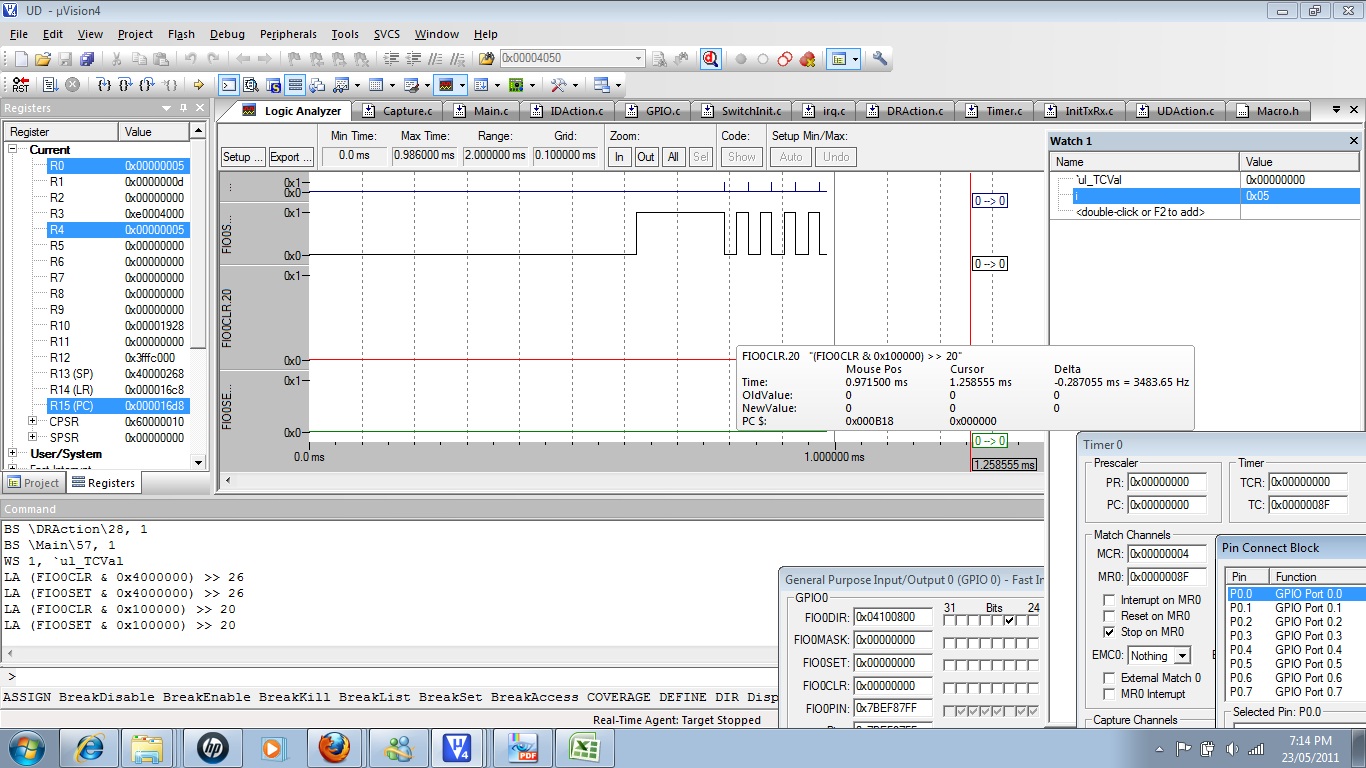
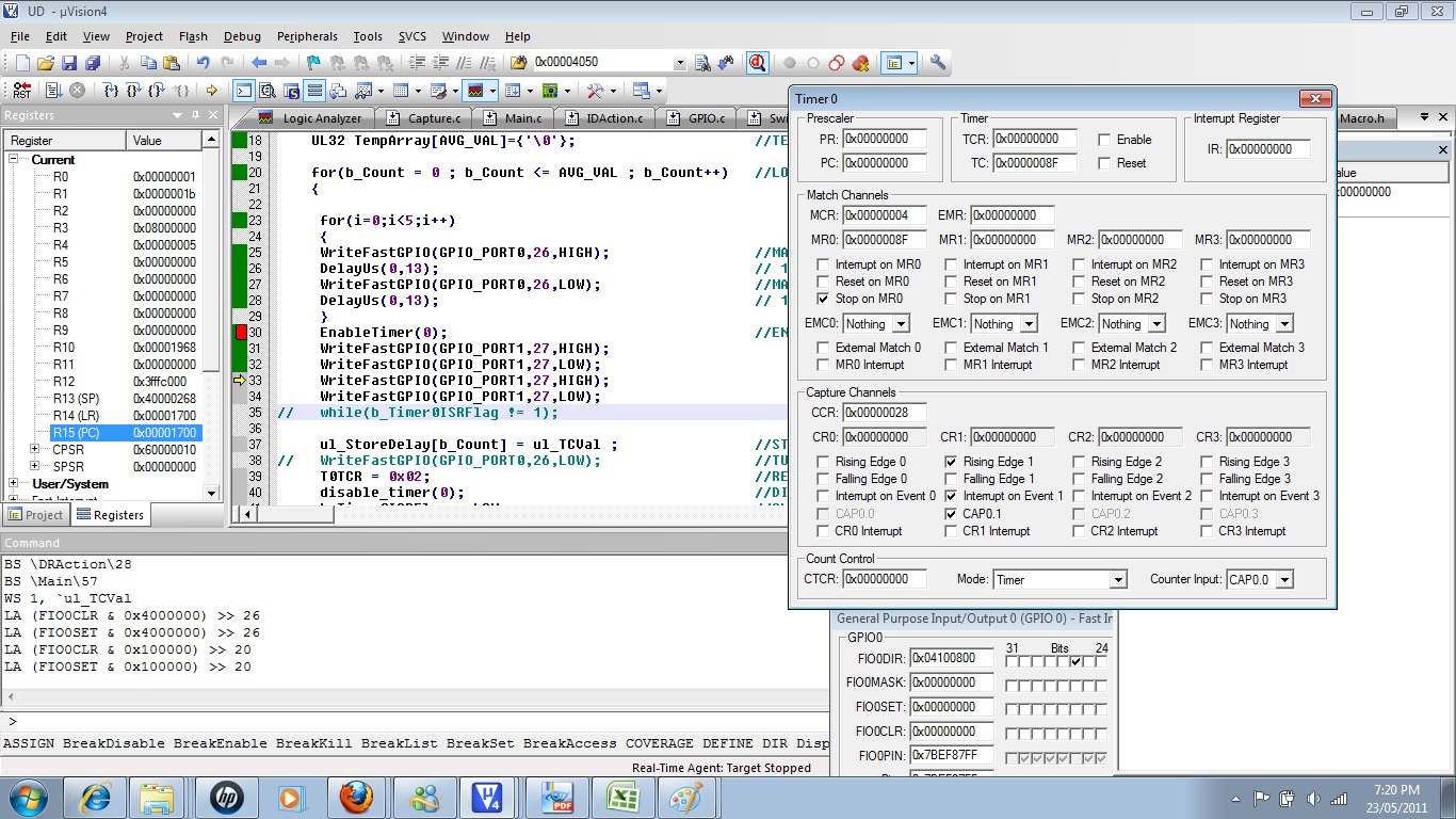
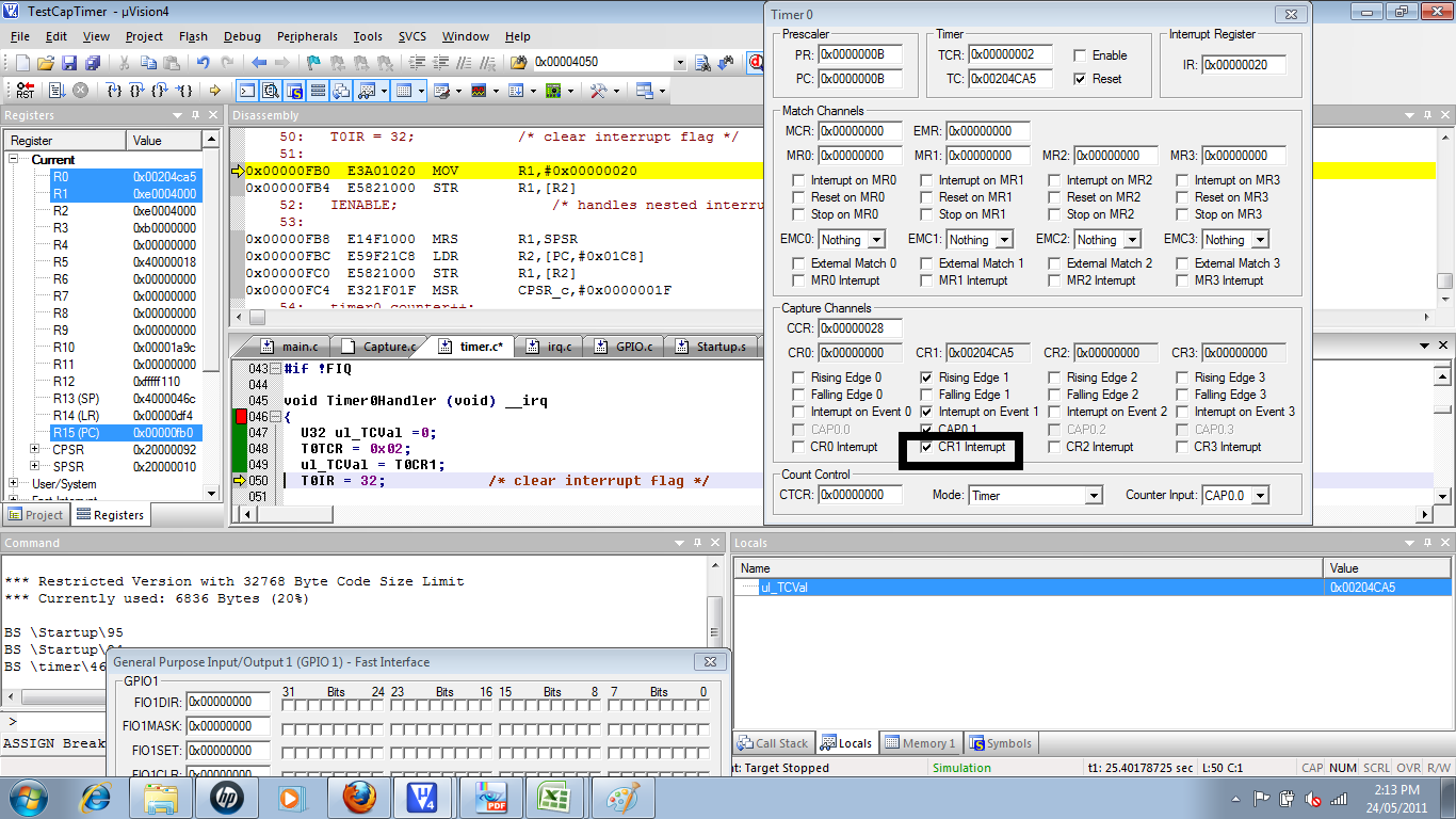
I am newbie to LPC family , I am engaged in a project in which I am transmitting 38khz square wave and after deflaction from an obstacle the receiver receives the frequency on CAP0[1] pin of LPC2364. I have managed to generate the 38k square wave but not able to capture the square wave. can any body just correct the below written code to capture the square wave..as my intention is to calculate the time required for the wave to travel and come back.
with this delay i can calculate the distance at which the object is kept.


U8 ConfCaptMode() //CONFIGURE THE PIN1.27 TO CAPTURE THE TIMER COUNTER 0 VALUE ON RISING EDGE
{

PINSEL3 = 0x00D00000; //SELECT CAP0[1] FUNCTIONALITY FOR 11 ACT AS GPIO[23 22].

EnableFastGPIO(GPIO_PORT1,27); //Enable GPIO_PORT1 PIN NUM 20
WriteFastGPIODirection(1,27,0); //PORT NUM 1,PIN NUM 27,DIRECTION INPUT.FAST IO

T0CCR = 0X01 ; //CAPTURE CONTROL REGISTER THE SEQUENCE 0-1 WILL CAUSE THE REGISTER TO LOAD WITH TC VALUE


return(0);
}


UL32 InitTxRx()
{
U8 b_ReadFlag =0; //READ THE STATUS OF RECEIVER PIN
U8 b_Count = 0; //TRANSMIT THE WAVE FOR B_COUNT TIMES
//TO CALCULATE THE AVERAGE DISTANCE

UL32 TempArray[AVG_VAL]={'\0'}; //TEMP ARRAY TO STORE AVERAGE DELAY

for(b_Count = 0 ; b_Count <= AVG_VAL ; b_Count++) //LOOP TO TRANSMIT AND RECEIVE THE FREQ AVG NUM OF TIMES
{


EnableTimer(0); //ENABLE TIMER I.E START TIMER

WriteFastGPIO(GPIO_PORT0,26,HIGH); //MAKE THE TX PIN HIGH FOR TRANSMITTER
DelayUs(0,13);
WriteFastGPIO(GPIO_PORT0,26,HIGH);
DelayUs(0,13);


while(b_ReadFlag != 1) //READ THE PIN STATUS
{

b_ReadFlag=ReadFastGPIO(GPIO_PORT1,27); //READ FAST GPIO

}

ul_TCVal = T0CR0 ; //COPY CAPTURE VALUE TO STORE IN GLOBAL DELAY VARIABLE

ul_StoreDelay[b_Count] = ul_TCVal ; //STORE THE DELAY IN GLOBAL ARRAY POSITION WISE

WriteFastGPIO(GPIO_PORT0,26,LOW); //TURN OFF THE TRANSMITTER

T0TCR = 0x02; //RESET TIMER

disable_timer(0); //DISABLE TIMER

}

for(b_Count=0 ; b_Count <= AVG_VAL ; b_Count++) //CALCULATE THE AVERAGE VALUE
{

TempArray[b_Count] = TempArray[b_Count] + ul_StoreDelay[b_Count];

ul_TCVal = (TempArray[b_Count]/AVG_VAL);

}


return(ul_TCVal);


}


if anybody can give idea through algorithm will also be helpful?
Basically how to capture a square wave and calculate the travelling time.
 

What compiler do you use?
I'm not familiar with EnableFastGPIO, or WriteFastGPIODirection but they seem to be using the fast GPIO, if this is the case then I don't see the part where you set port 0 &1 to FAST GPIO mode since the default is legacy GPIO.
You need to use SCS |=1;

PINSEL3 = 0x00D00000; is not valid, you need 0x00C00000 to set P1.27 to CAP0.1 function and P0.26 as GPIO.
0x00D00000 is wrong because it sets P1.26 to pinsel value "01" and this function of the pin is reserved in LPC2364 (and is USB in 2361/62)

Alex
 

Dear Alex,

please find the attached file which shows you simulated things like, the value loaded to select the Capture functionality is correct and not reserved for usb.
I ma using Lpc2364.

and for now you consider that those function which i am calling a writefastgpio is to write data on fast gpio.

Please suggest how to use capture mode if you have any example.
 

Attachments

  • Doc2.doc
    332 KB · Views: 90

You haven't read what I wrote, I didn't say that the CAP0.1 was wrong
0x00D00000 is wrong because it sets P1.26 to pinsel value "01" and this function of the pin is reserved in LPC2364 (and is USB in 2361/62)
P1.27 is correct but P1.26 is in a reserved value, actually your can see it in your second photo, P1.26 is not working as GPIO.
Also you didn't say anything about the SCS register, witing to fast GPIO will do nothing if you don't enable the fast GPIO using the SCS register.

Alex
 
Hi! Alex The value 0xc is correct by as we have configuration for USB to...we are connecting this board through USB to android phone.According to you it should be as below

Pin value
20 (0)
21 (0)
22 (1)
23 (1)
According to you this is correct .... but two configuration has been done in same statement ..which is confusing..i will change it..
 

Ok! thanks
I got it ! you can see the correction in the attached file.

Thanks
 

Attachments

  • Doc2.doc
    181 KB · Views: 100

LPC2364 doesn't have USB function for P1.26 anyway.
Now tell me about the SCS register, you have to set bit 0 to value "1" to enable the fast GPIO, have you done that?

ARM_SCS.jpg

Alex
 

Dear Alex,
Yes I a have added this line SCS |= 1 to my code.Please check the code
Now, check this one will this configure the PIN for capturing a square wave


U8 ConfCaptMode() //CONFIGURE THE PIN1.27 TO CAPTURE THE TIMER COUNTER 0 VALUE ON RISING EDGE
{

PINSEL3 = 0x00C00000; //SELECT CAP0[1] FUNCTIONALITY FOR 11 ACT AS GPIO[23 22].

SCS |= 1;

WriteFastGPIODirection(1,27,0); //PORT NUM 1,PIN NUM 27,DIRECTION INPUT.FAST IO

T0CCR = 0X05 ; //CAPTURE CONTROL REGISTER THE SEQUENCE 0-1 WILL CAUSE THE REGISTER TO LOAD WITH TC VALUE


return(0);
}


void WriteFastGPIODirection(U8 bPortNo, U8 bPinNo, U8 bDirection)
{
if(bPinNo > 31)
{
return;
}
switch(bPortNo)
{
case GPIO_PORT0:
if(bDirection) /*output*/
FIO0DIR |= (1 << bPinNo);
else /*input*/
FIO0DIR &= (~(1 << bPinNo));
break;
case GPIO_PORT1:
if(bDirection) /*output*/
FIO1DIR |= (1 << bPinNo);
else /*input*/
FIO1DIR &= (~(1 << bPinNo));
break;
case GPIO_PORT2:
if(bDirection) /*output*/
FIO2DIR |= (1 << bPinNo);
else /*input*/
FIO2DIR &= (~(1 << bPinNo));
break;
case GPIO_PORT3:
if(bDirection) /*output*/
FIO3DIR |= (1 << bPinNo);
else /*input*/
FIO3DIR &= (~(1 << bPinNo));
break;
case GPIO_PORT4:
if(bDirection) /*output*/
FIO4DIR |= (1 << bPinNo);
else /*input*/
FIO4DIR &= (~(1 << bPinNo));
break;
}
}

---------- Post added at 14:55 ---------- Previous post was at 14:54 ----------

Dear Alex,
Yes I a have added this line SCS |= 1 to my code.Please check the code
Now, check this one will this configure the PIN for capturing a square wave


U8 ConfCaptMode() //CONFIGURE THE PIN1.27 TO CAPTURE THE TIMER COUNTER 0 VALUE ON RISING EDGE
{

PINSEL3 = 0x00C00000; //SELECT CAP0[1] FUNCTIONALITY FOR 11 ACT AS GPIO[23 22].

SCS |= 1;

WriteFastGPIODirection(1,27,0); //PORT NUM 1,PIN NUM 27,DIRECTION INPUT.FAST IO

T0CCR = 0X05 ; //CAPTURE CONTROL REGISTER THE SEQUENCE 0-1 WILL CAUSE THE REGISTER TO LOAD WITH TC VALUE


return(0);
}


void WriteFastGPIODirection(U8 bPortNo, U8 bPinNo, U8 bDirection)
{
if(bPinNo > 31)
{
return;
}
switch(bPortNo)
{
case GPIO_PORT0:
if(bDirection) /*output*/
FIO0DIR |= (1 << bPinNo);
else /*input*/
FIO0DIR &= (~(1 << bPinNo));
break;
case GPIO_PORT1:
if(bDirection) /*output*/
FIO1DIR |= (1 << bPinNo);
else /*input*/
FIO1DIR &= (~(1 << bPinNo));
break;
case GPIO_PORT2:
if(bDirection) /*output*/
FIO2DIR |= (1 << bPinNo);
else /*input*/
FIO2DIR &= (~(1 << bPinNo));
break;
case GPIO_PORT3:
if(bDirection) /*output*/
FIO3DIR |= (1 << bPinNo);
else /*input*/
FIO3DIR &= (~(1 << bPinNo));
break;
case GPIO_PORT4:
if(bDirection) /*output*/
FIO4DIR |= (1 << bPinNo);
else /*input*/
FIO4DIR &= (~(1 << bPinNo));
break;
}
}

---------- Post added at 15:09 ---------- Previous post was at 14:55 ----------

Oh !!! Great Workk!!!
 

T0CCR = 0X05 ; sets CAP0.0 to capture at rising edge and generate interrupt.
If you want CAP0.1 to capture on rising edge and generate interrupt you must use T0CCR = 0X28;

Alex
 
Can I simulate the capture interrupt on Keil or do i need a board....i.e external interrupt...
Please suggest...
Thanks and Regards
Hrishikesh.
 

Yes the capture can be simulated fine, Just use the GPIO screen and change the state of P1.27 so that it is detected (you need a rising edge, turn off and on again), you will get an interrupt and the value of the timer will be stored in the capture register.

Alex
 

for(i=0;i<5;i++)
{
WriteFastGPIO(GPIO_PORT0,26,HIGH); //MAKE THE TX PIN HIGH FOR TRANSMITTER
DelayUs(0,13); // 13 US
WriteFastGPIO(GPIO_PORT0,26,LOW); //MAKE THE RX PIN LOW FOR TRANSMITTER
DelayUs(0,13); // 13 US
}
EnableTimer(0); //ENABLE TIMER I.E START TIMER
WriteFastGPIO(GPIO_PORT1,27,HIGH);
WriteFastGPIO(GPIO_PORT1,27,LOW);
WriteFastGPIO(GPIO_PORT1,27,HIGH);
WriteFastGPIO(GPIO_PORT1,27,LOW);

Hi Alex !! Please have a look at this i am generating 40khz wave on pin .. as shown in attacthed image, i have tested my timer interrupt works in normal code but it fails to go to the interrupt when i make the port1 pin 27 cap0[1] pin high low !! can u guess what could be the problem.


Please reply
Thanks and regards
Hrishikesh
 

I don't think you can't use this to change the pin state from the code, this is no longer a GPIO pin
WriteFastGPIO(GPIO_PORT1,27,HIGH);
WriteFastGPIO(GPIO_PORT1,27,LOW);
WriteFastGPIO(GPIO_PORT1,27,HIGH);
WriteFastGPIO(GPIO_PORT1,27,LOW);

I meant to use the checkboxes available in the debugging screen of uvision, from there (GPIO1 fast interface) uncheck and check again P1.27 of Pins.
Also add a breakpoint to your interrupt to stop execution when it happens.

Alex
 
Dear Alex!

Can u check the complete code for timer capture . i tried by checking unchecking the port pin but the interrupt is not occuring. my normal timer interrupt is taking palce..but for now i have commented interrupt on match register in handler if u could suggest some correction in the code.


thanks and regards
Hrishikesh
 

Attachments

  • TestCapTimer.rar
    216.1 KB · Views: 103

Your code (the capture part) works fine.
I have used the GPIO fast interface>>port 1 to uncheck and check P1.27 and it gave an interrupt.
Start debugging, add a breakpoint in the first line of the interrupt and press the run (F5) the button next to RST (reset).
You will get the intterupt but you clear the wrong interrupt flag of MAT0.0 instead of CAP0.1 so you keep getting interupts as soon as you exit from it because CAP0.1 flag in not cleared.

T0IR = 1; /* Clear MAT0.0 interrupt flag */
T0IR = 2; /* Clear MAT0.1 interrupt flag */
T0IR = 4; /* Clear MAT0.2 interrupt flag */
T0IR = 8; /* Clear MAT0.3 interrupt flag */
T0IR = 16; /* Clear CAP0.0 interrupt flag */
T0IR = 32; /* Clear CAP0.1 interrupt flag */ << you need to use this one for CAP0.1

Alex
 
Dear Alex!
First of all thank you very much .. this was first experience to have a problem solved ...with help of a internet friend...thank you very much.
Please have a look at the Picture.
when i am simulating do i need to set the Check mark for CR1 interrupt manually ...bcoz when i am putting a check mark on the CR1 it goes to Interrupt handler else it remains in while loop.
I also think that when i am putting check marks for pin 1.27 the CR1 interrupt should be generated ?

In case of real time , this will interrupt will be automatically set ?


hrishikesh.
 

You can tick the CR1 interrupt checkbox manually to get the interrupt but the way I have done it is as I have described in my previous post.
I have used the P1.27 in the GPIO window (in the lower left side of your picture), just unchecked and check again the P1.27 in the last line named "pins", it will automatically set the CR1 interrupt flag (because you generate a rising edge).
you can do it both ways with the same result, the difference is that changing the CR1 flag will always give an interrupt but the pin change will only give an interrupt if the pin function is set correctly to capture input.
And yes in a real circuit the flag will be set automatically if everything is set up correctly.

Alex
 

Dear Alex!

As per your Post , Have made these changes in my code

1.In Interrupt handler code i have replaced TOIR = 0x01 with 0x32.
2.And as per our previous discussion, the pin functionality for capture is also configured as below


SCS |= 1; //for fast gpio
PINSEL3 = 0x00C00000; //for CAP0[1];

WriteFastGPIODirection(1,27,0); //DIRECTION AS INPUT

switch(bUnit)
{
case NANO_SEC:
case MICRO_SEC:
fTime = (fTime / (F32)1000000.0);
dwTime = (U32)(((F32)TIMER_CLOCK*fTime) - 1);
break;
default:
return 0; //failed to configure timer
case MILLI_SEC:
fTime = (fTime / (F32)1000.0);
dwTime = (U32)(((F32)TIMER_CLOCK*fTime) - 1);
break;
case SECOND:
dwTime = (U32)(((F32)TIMER_CLOCK*fTime) - 1);
break;
}

T0PR = dwTime; // 1microsecond

if(u8Channel == CHANNEL0 && u8CaptEvent == RISING_EDGE)
u16Data = 0x05;//interrupt enable ,RISING_EDGE
else if(u8Channel == CHANNEL0 && u8CaptEvent == FALLING_EDGE)
u16Data = 0x06;//interrupt enable ,FALLING_EDGE

if(u8Channel == CHANNEL1 && u8CaptEvent == RISING_EDGE)
u16Data = 0x28;//interrupt enable ,RISING_EDGE .................................i am loading these value
else if(u8Channel == CHANNEL1 && u8CaptEvent == FALLING_EDGE)
u16Data = 0x30;//interrupt enable ,FALLING_EDGE


T0CCR = 0x28; //Cap.0 input on Rising Edge and interrupt enable
T0TCR = 1; // Timer0 Enable

3. I have set a break point at the first statement of my handler code ...
but when i am toggling the fast gpio pins there is no interrupt set on the CR1 pin..

as we enable timer interrupt with help of vic addresses do i need to enable the CR1 interrupt to ?? please reply....


hrishikesh.
 

.In Interrupt handler code i have replaced TOIR = 0x01 with 0x32.
I didn't write hexadecimal 32 but decimal 32 , you had T0IR = 1; and the correct is T0IR = 32;
T0IR = 32; /* Clear CAP0.1 interrupt flag */ << you need to use this one for CAP0.1
if you want to use hexadecimal then it is T0IR = 0x20; but there is no need to write it like that.

WriteFastGPIODirection(1,27,0); //DIRECTION AS INPUT
There is no point to do that, when you set an alternative function to any pin then the direction register is ignored and the pin uses (overrides) the direction with the appropriate direction of the selected function, CAP is always an input.

The code that you have attached in the previous post was working fine, I have only changed the T0IR = 32;.
Are you changing P1.27 checkbox and you don't get an interrupt?

The project I have used was TestCapTimer.uvproj , the interrupt that is called is the one in line 45 of timer.c so use the breakpoint in line 46

Alex
 

Status
Not open for further replies.

Similar threads

Part and Inventory Search

Welcome to EDABoard.com

Sponsor

Back
Top