Continue to Site

Welcome to EDAboard.com

Welcome to our site! EDAboard.com is an international Electronics Discussion Forum focused on EDA software, circuits, schematics, books, theory, papers, asic, pld, 8051, DSP, Network, RF, Analog Design, PCB, Service Manuals... and a whole lot more! To participate you need to register. Registration is free. Click here to register now.

[SOLVED] Lpc2364 - Capture Timer 0 channel 1

Status
Not open for further replies.
Hi!

I tried it both ways replacing T0IR = 32 and 0x20..but its not getting the interrrupt i also removed the GPIO functionality part.
Yes i am clicking on the check boxes.
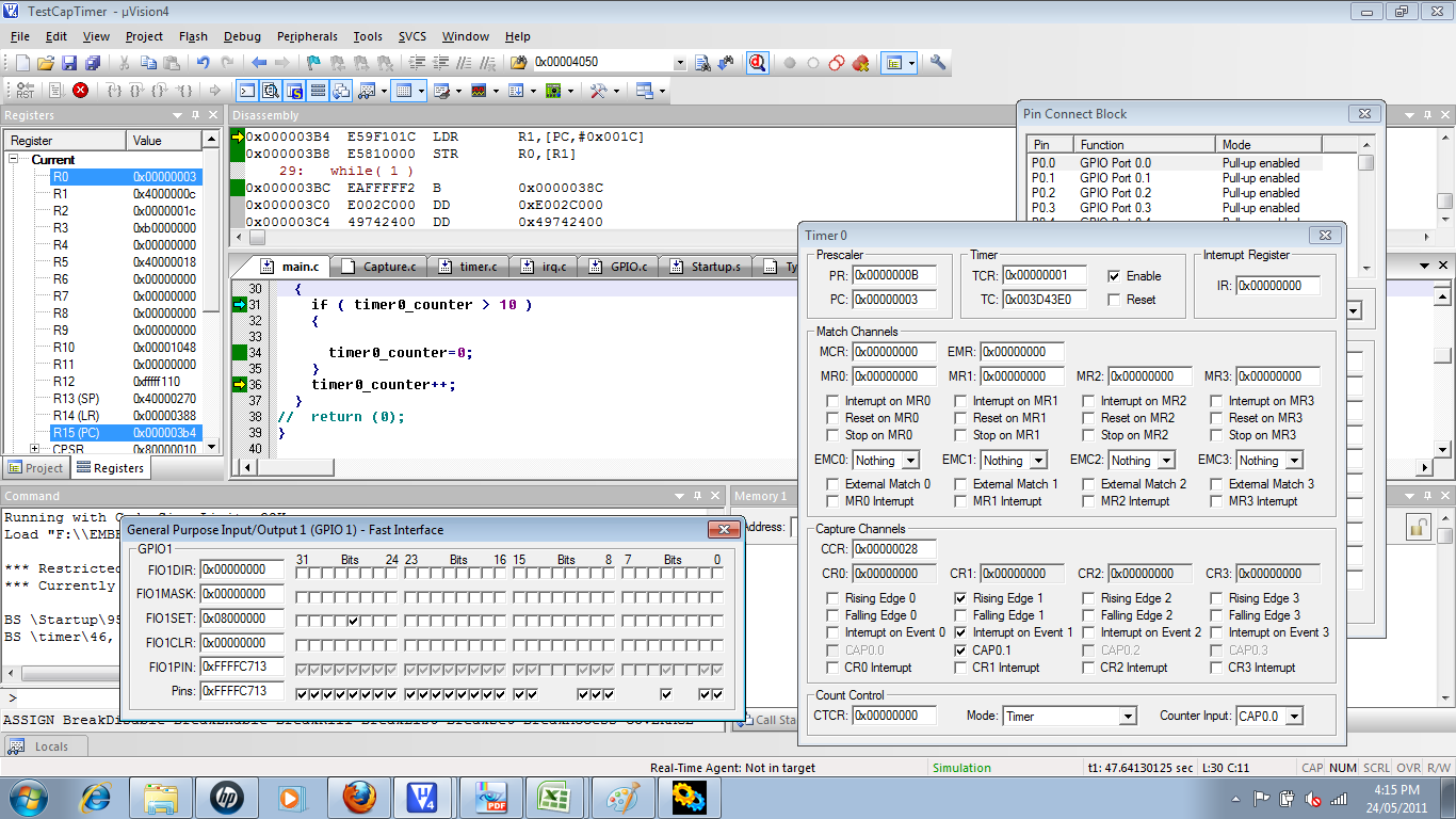
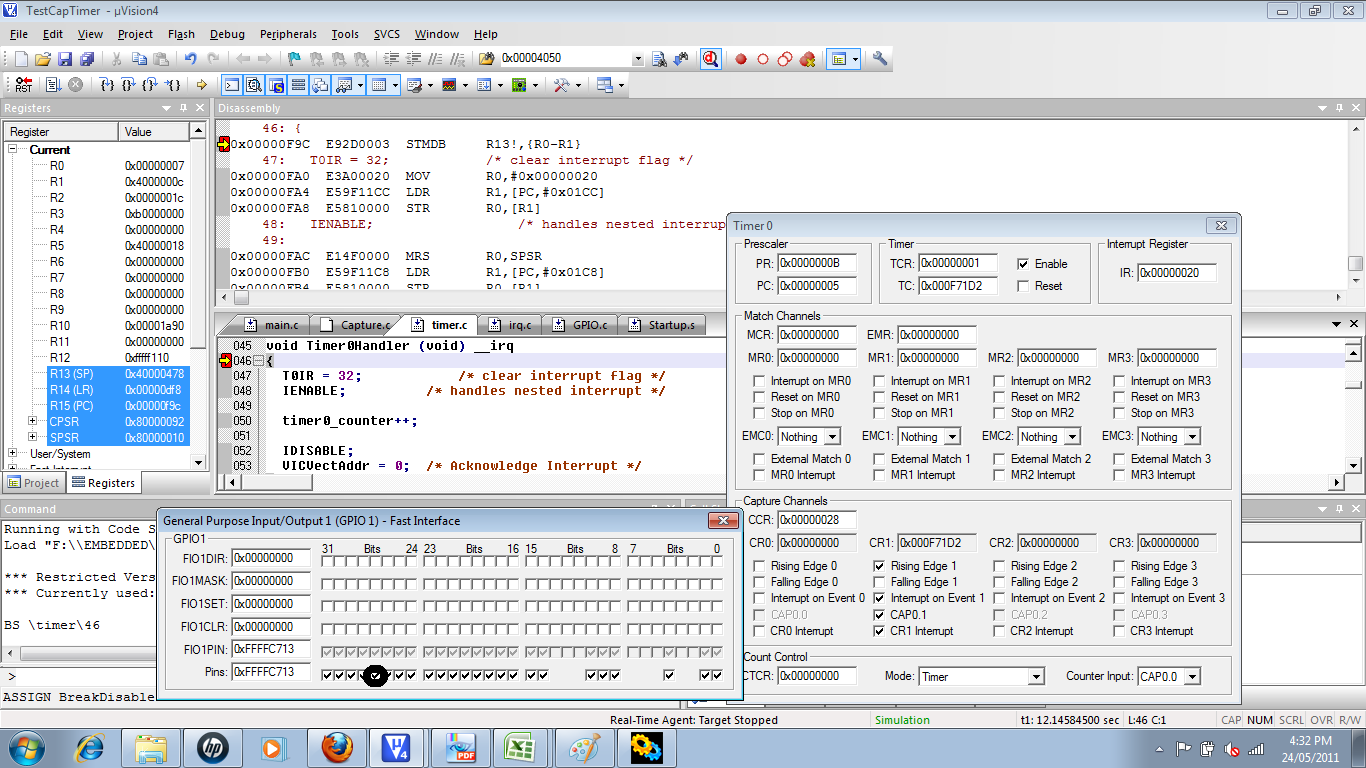
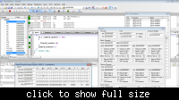
when i manually check the CR1 it goes in interrupt which is wrong!!!!!otherwise it remains in the while loop.
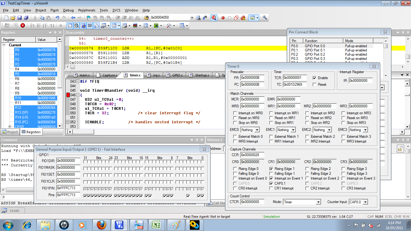
Similarly you can also see the breakpoint in the first image at line 46.


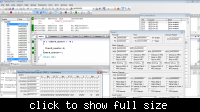
I have attached the images-> simulation time.


Don't use the FIOSET / FIOCLR register checkbox, these can't change the port because the pin P1.27 is not GPIO anymore.
Use the "Pins" checkbox , it is the last line in the dialog, uncheck and check the pin from there.

Alex
 
Hi!!

Just check if this is correct ?
should i tick the encircled pin high - low if it is....
Then i am getting the interrupt ....Please reply and see the attached image.


Thanks and Regards
hrishikesh.
 

Yes this is the right checkbox, it is the actual state of the pin, it is the only way to change the pin state when it isn't a GPIO

Alex
 
Thanks alot Alex....will meet with new Issue...be ready my friend.

Hrishikesh

---------- Post added at 16:56 ---------- Previous post was at 16:54 ----------

Thanks alot Alex....will meet with new Issue...be ready my friend.

Hrishikesh:lol:
 

Status
Not open for further replies.

Similar threads

Part and Inventory Search

Welcome to EDABoard.com

Sponsor

Back
Top