Continue to Site

Welcome to EDAboard.com

Welcome to our site! EDAboard.com is an international Electronics Discussion Forum focused on EDA software, circuits, schematics, books, theory, papers, asic, pld, 8051, DSP, Network, RF, Analog Design, PCB, Service Manuals... and a whole lot more! To participate you need to register. Registration is free. Click here to register now.

[SOLVED] LPC2138 simulation in proteus not working

Status
Not open for further replies.

ameriq

Junior Member level 3
Joined
Oct 1, 2007
Messages
29
Helped
4
Reputation
8
Reaction score
4
Trophy points
1,283
Location
Pakistan
Visit site
Activity points
1,487
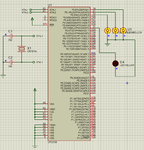
Hi, I am using proteus 7.4 and just beginning ARM. Here is my basic circuit. In properties i have set the clock freq to 12MHz.
I just want to blink an LED, at present just to set P0.7 high. But is not getting high, instead it stays in indiffterent state.
The code written in keil uvision 4 shows ok in debugger.


Code C - [expand]
1
2
3
4
5
6
7
8
9
10
11
12
13
14
15
16
17
18
19
20
#include <LPC213X.H>
void delay(int);
int main(void)
{
    IO0DIR = 0x00000080;
    while(1)
    {
        IO0SET=0x00000080;
        
     }
     return 0;
}
 
void delay(int a)
{
    unsigned int i;
        for(i=0;i<=a;i++);
    
    //return 0;
}


LPC2138.gif
 
Last edited by a moderator:

Sorry... im not use this... but try this code from keil examples:
Code:
/******************************************************************************/
/*  This file is part of the uVision/ARM development tools                    */
/*  Copyright KEIL ELEKTRONIK GmbH 2002-2004                                  */
/******************************************************************************/
/*                                                                            */
/*  BLINKY.C:  LED Flasher                                                    */
/*                                                                            */
/******************************************************************************/
                  
#include <stdio.h>                         /* standard I/O .h-file */
[B]#include <LPC21xx.H>                       /* LPC21xx definitions  */[/B]

extern void init_serial (void);            /* Initialize Serial Interface     */


void sendhex (int hex) {                   /* Write Hex Digit to Serial Port  */
  if (hex > 9) putchar('A' + (hex - 10));
  else         putchar('0' +  hex);
}

void sendstr (char *p) {                   /* Write string */
  while (*p) {
    putchar (*p++);
  }
}


[B]void delay (void) {                        /* Delay function */
  unsigned int cnt;
  unsigned int val;

  ADCR |= 0x01000000;                      /* Start A/D Conversion */
  do {
    val = ADDR;                            /* Read A/D Data Register */
  } while ((val & 0x80000000) == 0);       /* Wait for end of A/D Conversion */
  ADCR &= ~0x01000000;                     /* Stop A/D Conversion */
  val = (val >> 6) & 0x03FF;               /* Extract AIN0 Value */

  sendstr ("\nAIN0 Result = 0x");          /* Output A/D Conversion Result */
  sendhex((val >> 8) & 0x0F);              /* Write 1. Hex Digit */
  sendhex((val >> 4) & 0x0F);              /* Write 2. Hex Digit */
  sendhex (val & 0x0F);                    /* Write 3. Hex Digit */

  val = (val >> 2) << 12;                  /* Adjust Delay Value */
  for (cnt = 0; cnt < val; cnt++);         /* Delay */
}


int main (void) {
  unsigned int n;

  IODIR1 = 0x00FF0000;                     /* P1.16..23 defined as Outputs  */
  ADCR   = 0x002E0401;                     /* Setup A/D: 10-bit AIN0 @ 3MHz */[/B]
  init_serial();                           /* Initialize Serial Interface   */

 [B] while (1) {                              /* Loop forever */
    for (n = 0x00010000; n <= 0x00800000; n <<= 1) {
      /* Blink LED 0, 1, 2, 3, 4, 5, 6, 7 */
      IOSET1 = n;                          /* Turn on LED */
      delay();                             /* Delay */
      IOCLR1 = 0x00FF0000;                 /* Turn off LEDs */
	}
  }
}[/B]
 

@jayanth.devarayanadurga

I am going to learn Proteus, what are the things to remember and how to run schematics and is there you having any documents about it.....
 

In your program PINSEL function is missing.

It is used for select the Pin function.

PINSEL0=0x00000000;

use this above IO0DIR register.

I hope its helps you.
 

I am using proteus 7.4 and just beginning ARM. Here is my basic circuit. In properties i have set the clock freq to 12MHz.
I just want to blink an LED, at present just to set P0.7 high. But is not getting high, instead it stays in indiffterent state.

I believe the source of the issue is the lack of an attached crystal.

If I remember correctly, unlike some other microcontrollers, when simulating a design with an NXP LCP21xx series ARM in Proteus, you must provide the internal oscillator an appropriate crystal.

Try attaching a crystal with a value of between 10MHz and 25MHz to the XTAL1 and XTAL2 along with a matched pair of 38pF capacitors as detailed in the devices datasheet.

Reference: , Section: 4.4 Crystal Oscillator, Page: 24 - 25
While an input signal of 50-50 duty cycle within a frequency range from 1 MHz to 50 MHz
can be used by the LPC213x if supplied to its input XTAL1 pin, this microcontroller’s
onboard oscillator circuit supports external crystals in the range of 1 MHz to 30 MHz only.
If the on-chip PLL system or the boot-loader is used, the input clock frequency is limited to
an exclusive range of 10 MHz to 25 MHz.

BigDog
 

I don't think that the problem is caused from the missing crystal, LPC213x series in proteus have a clock frequency property (set to 10MHz by default but can be changed in the mcu properties dialog) , this is the frequency that the PLL gets which is then multiplied/divided based on the code settings

Alex

- - - Updated - - -

I would suggest you attach the compete uvision project files including proteus schematic so we can check what is wrong
 

You have used 5V ass VDD. Set it to 3.3V and it will work. You can do that in menu or use a 3.3V battery to power the uC.


Configure Power Rail... dialog Set VCC/VDD to 3.3V instead of 5V.
 

In proteus Power terminal is 5V how did you change its properties you only changed name to +3.3 . Your code is ok and use two 1.5v cells in series . It works i have personally run it now on Proteus.
 

I think he just changed the label to +3.3V or maybe he added a text showing 3.3V not power properties.
The Vcc triangle symbol has only one label and if you set it to +3.3 then the voltage it provides becomes 3.3v


If the supply voltage was wrong he would get a message like

94087d1374926516-vcc_error.jpg
 

Attachments

  • Vcc_error.jpg
    Vcc_error.jpg
    13.6 KB · Views: 176

Thank you dear friends for the valuable input. I have tried all suggestion but not succesful. I am posting the folder with proteus 7.4 file and keil uvision 4 project. your valuable comments will be helpful.
 

Attachments

  • arm7.rar
    81.5 KB · Views: 111

Code fixed.

There was nothing wrong with the code, he was trying to
I just want to blink an LED, at present just to set P0.7 high. But is not getting high, instead it stays in indiffterent state.

And this is exactly what happens if you simulate the files he attached, worked fine for me
 

I saw the circuit. It had LEDs on 0.0, 0.1 and 0.2 and code was setting 0.7 so I changed the code to set 0.0, 0.1 and 0.2.

Even I have the same problem. 0.7 doesn't light up. 0.7 to 0.31 is always grayed out.
 
Last edited:

Status
Not open for further replies.

Similar threads

Part and Inventory Search

Welcome to EDABoard.com

Sponsor

Back
Top