mr_byte31
Full Member level 5
Hi All,
I am planning to build a 5v power supply which can provide at least 50A. I found many project on internet that use MOT (Microwave oven transformer)
it can produce a lot of current. I am focusing now on the losses and low ripple DC voltage.
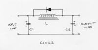
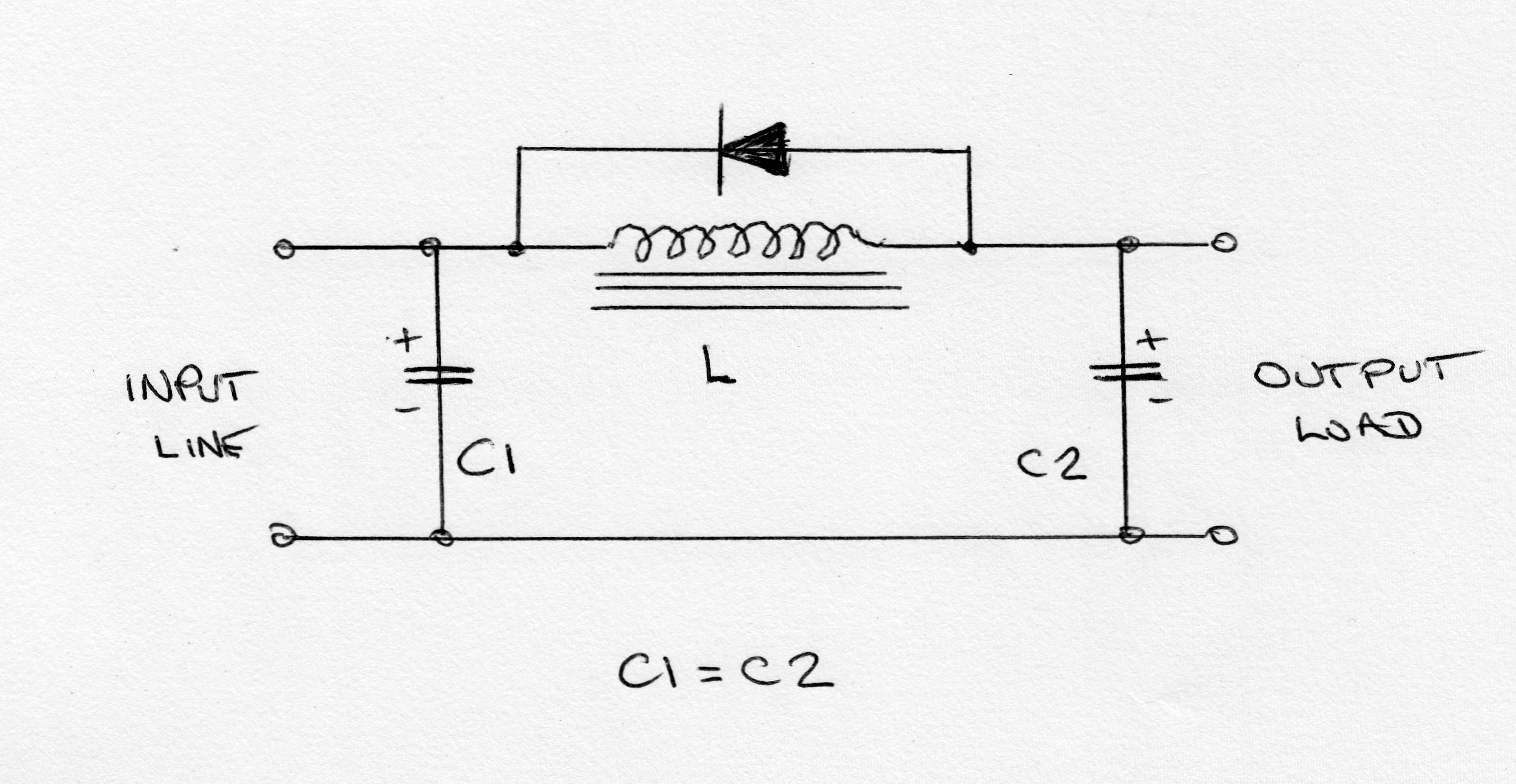
I am planning to use Pi-Filter to remove the AC ripple voltage (Forget about values in figure, I just add it as reference):
**broken link removed**
I will configure the secondary windings to have 6.4 v AC to overcome the losses on the rectifier
I have two points here
losses:
-------
The bridge rectifies would reduce waste 2x0.7v = 1.4 v
The losses would be 1.4 v x 50 A = 70W
the remaining voltage would be (6.4-1.4=5 v), the power here would be = 5 v x 50 A = 250 W
we get a efficiency of approx = 1- 70/250 = 72% !! I think this is low
any idea how to improve this ?
AC ripples:
-----------
is it possible to have a very low AC ripples at this high current using Pi-filter? (forget about the C and L values in figure)
I am planning to build a 5v power supply which can provide at least 50A. I found many project on internet that use MOT (Microwave oven transformer)
it can produce a lot of current. I am focusing now on the losses and low ripple DC voltage.
I am planning to use Pi-Filter to remove the AC ripple voltage (Forget about values in figure, I just add it as reference):
**broken link removed**
I will configure the secondary windings to have 6.4 v AC to overcome the losses on the rectifier
I have two points here
losses:
-------
The bridge rectifies would reduce waste 2x0.7v = 1.4 v
The losses would be 1.4 v x 50 A = 70W
the remaining voltage would be (6.4-1.4=5 v), the power here would be = 5 v x 50 A = 250 W
we get a efficiency of approx = 1- 70/250 = 72% !! I think this is low
any idea how to improve this ?
AC ripples:
-----------
is it possible to have a very low AC ripples at this high current using Pi-filter? (forget about the C and L values in figure)
Last edited by a moderator: