Continue to Site

Welcome to EDAboard.com

Welcome to our site! EDAboard.com is an international Electronics Discussion Forum focused on EDA software, circuits, schematics, books, theory, papers, asic, pld, 8051, DSP, Network, RF, Analog Design, PCB, Service Manuals... and a whole lot more! To participate you need to register. Registration is free. Click here to register now.

Low voltage cut off -- help please.

Status
Not open for further replies.

lee321987

Member level 5
Joined
Apr 3, 2011
Messages
86
Helped
1
Reputation
2
Reaction score
1
Trophy points
1,288
Activity points
1,987
Hello.
I'm trying to build a low-voltage cut off circuit.
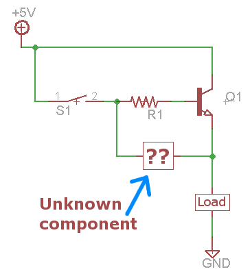
The idea is a momentary switch turns on a transistor which powers the circuit, some (unknown) component in the circuit will instantly begin powering the base of the transistor.
When a certain low voltage is reached this unknown component will stop powering the base of the transistor (i.e. the switch will be required to power on again).

Is there a way to build this with any common components?
Could an LM431 (a.ka. TL431) shunt regulator do it?
Schematic:
 

It should be quite simple to do what you want, but the circuit will be different to what you showed.

A couple of questions first:

  • With your idea the power to the load is turned on when the switch is momentarily pressed, but how do you plan to switch it off? Is there another button for that?
  • What is the load? We need to know how much current needs to be switched.
  • Is it only for 5V operation? I'm wondering what the maximum supply voltage might be, and how low it can go before the load is switched off.

Another way to do it is to have a circuit that switches off the load when the supply voltage is too low, and switches it back on automatically when the voltage is high enough again.

I'm not sure what would be best for your purpose.
 
Yes, you can do it. See the diagram
 

Attachments

  • ON_OFF voltage.png
    ON_OFF voltage.png
    26.2 KB · Views: 243
LVcut.gif

LOW VOLTAGE CUT-OUT

Circuit will detect when the voltage of a 12v battery reaches a low level. This is to prevent deep-discharge or maybe to prevent a vehicle battery becoming discharged to a point where it will not start a vehicle. Uses hysteresis, that represent a feature where the upper and lower detection-points are separated by a gap.
Normally, the circuit will deactivate the relay when the voltage is 10v and when the load is removed. The battery voltage will rise slightly by as little as 50mV and turn the circuit ON again. This is called "Hunting." The off/on timing has been reduced by adding the 100u. But to prevent this totally from occurring, a 10R to 47R is placed in the emitter lead. The circuit will turn off at 10v but will not turn back on until 10.6v when a 33R is in the emitter.
The value of this resistor and the turn-on and turn-off voltages will also depend on the resistance of the relay.
 
@godfreyl
There will be no button to turn it off -- i want to power an LCD clock with NiMH batteries. Once they fall below a certain voltage, power to the clock will be cut -- then i'll remove & recharge the batteries, reinstall and press the button to power-on.

I want the manual turn-on required because i don't want it turning off-on-off-on a lot (because the battery voltage will go up when they are no longer powering the clock).

The clock draws 4.7mA typical, and 89mA when the back light button is pressed (lasts just 5 seconds).
 

Yes, you can do it. See the diagram
What is the yellow component? I would understand the circuit if that was an npn transistor, but if it is a thyristor I don't see how it will switch off when the voltage is too low.

...This is called "Hunting."...
But to prevent this totally from occurring, a 10R to 47R is placed in the emitter lead.
Nice - simple and elegant. I presume it relies on the hysteresis of the relay itself. i.e. The switch on current of the coil is greater than the drop out current.

I think a preference for solid state or relay switching would depend on the load. If solid state, I would prefer to use a common-emitter (or common-source) switching device to minimize the voltage drop.
 
What is the yellow component? I would understand the circuit if that was an npn transistor, but if it is a thyristor I don't see how it will switch off when the voltage is too low.

Would it work if it's an LM431 shunt regulator?
 

The clock draws 4.7mA typical, and 89mA when the back light button is pressed (lasts just 5 seconds).
OK. No sense using a relay then - a transistor will be cheaper and waste less power.

What's the normal operating voltage and the voltage at which the clock should be disconnected?
 
OK. No sense using a relay then - a transistor will be cheaper and waste less power.

What's the normal operating voltage and the voltage at which the clock should be disconnected?
3.6V = normal.
3V = cut off voltage.
 

Would it work if it's an LM431 shunt regulator?
Yes, that makes sense. (I didn't recognize the symbol).

I would simplify the circuit a bit though, as shown in the pic below.


---------- Post added at 12:55 ---------- Previous post was at 12:52 ----------

TL431 as required...
:roll:
Ok, Ok, got it now - clearly I need another cup of coffee. :oops:
 
Status
Not open for further replies.

Similar threads

Part and Inventory Search

Welcome to EDABoard.com

Sponsor

Back
Top