Continue to Site

Welcome to EDAboard.com

Welcome to our site! EDAboard.com is an international Electronics Discussion Forum focused on EDA software, circuits, schematics, books, theory, papers, asic, pld, 8051, DSP, Network, RF, Analog Design, PCB, Service Manuals... and a whole lot more! To participate you need to register. Registration is free. Click here to register now.

[SOLVED] Low Noise Amplifier Design Modification

Status
Not open for further replies.

Minchuu

Junior Member level 1
Joined
May 14, 2021
Messages
16
Helped
0
Reputation
0
Reaction score
0
Trophy points
1
Activity points
156
Hello,

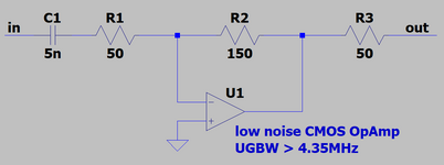
I was searching through CMOS LNA designs and I found this in GitHub and I think it's perfect for my application except for the frequency. For this, I will need a frequency range of 0.65MHz to 1.45 MHz instead of the 2.4 GHz in the original design.

Can you guys point out the inductors and capacitors I will need to change in the schematic and what is the equation I will need to use to compute for the new values in order to have 0.65 to 1.45 MHz frequency?

Thanks in advance.
LNA_Noise_Response.png
 

Hi,
2.45GHz is RF, so people use RF amplifier there, but under 10MHz everything is just, hmm.... pulsing DC.
This LNA is not too good choice, to amplify 1.45MHz a low noise CMOS OPAmp circuit should be enough which doesn't require huge and heavy inductors, linearity is not an issue, consumption is lower.
 

This LNA is not too good choice, to amplify 1.45MHz a low noise CMOS OPAmp circuit should be enough which doesn't require huge and heavy inductors, linearity is not an issue, consumption is lower.
Hi, thanks for the reply! I am a student, and unfortunately my project specifically specified that an LNA stage is required. So sadly, I still need a LNA even though it is not the best option for the frequency range. Would you perhaps have an LNA topology to suggest that will have a response and not just pulsing DC? I'm sure it won't be required of us if it's impossible (I think).

Thanks in advance.
 

Hard to recommend a circuit without knowing specifications. How much gain you need, does it require impedance matching, how much noise figure you need, supply range, max. consumption... an LNA has more parameters than bandwidth.
 

Hard to recommend a circuit without knowing specifications. How much gain you need, does it require impedance matching, how much noise figure you need, supply range, max. consumption... an LNA has more parameters than bandwidth.
Hello, thanks for the comment. Besides the 0.65 - 1.45 MHz BW, I will need a NF less than 3 dB, a power gain of approx. 10 dB, an IIP3 greater than -5 dBm, and an input and output impedance of 50 ohms. I apologize for not putting it in the first post. Supply range and max. consumption wouldn't be too much of a consideration in this project since it will be purely through simulations (though I presume it would have to be semi-realistic values, anyways).

Thanks in advance.
 

Well, I still think a simple OpAmp circuit might be enough. I have attached one, pretty simple, with prameter values on the scheamtic you can cover most of your specifications, but the IIP3 will be determined by the supply voltage and OpAmp output stage and I haven't calculate from NF requirement the necessary OpAmp input referred noise, but 3dB sounds normal, I guess you can design or pick a discrete one easily.
 

Attachments

  • lna.png
    lna.png
    12.8 KB · Views: 128

Hi,

does it just need to be a "low noise amplifier", or does it need to ba an "RF LNA"?

I currently don´t see the need for RF in the Gigahertz range.

Klaus
 

I currently don´t see the need for RF in the Gigahertz range.

You mean Megahertz range. And I see, because it is a school project. I guess they have to show they took into consideration RF things like NF,IIP3 or matching and maybe they don't really want to care with analog CMOS design.
 

does it just need to be a "low noise amplifier", or does it need to ba an "RF LNA"?
It just needs to be a low noise amplifier.

You mean Megahertz range. And I see, because it is a school project. I guess they have to show they took into consideration RF things like NF,IIP3 or matching and maybe they don't really want to care with analog CMOS design.
This is exactly my situation right now. So unfortunately I cannot use the OpAmp suggestion, but thank you very much for that nonetheless.

And we weren't given much resources, just the specs. And when I google 'LNA design methodology' or any other variations, I only see in the Gigahertz range, which is not what I need.

That is why I resorted to asking here. Any help will be very much appreciated.

Thank you very much!
 

Well, not clear why you cannot use the OpAmp circuit then.

It will be a CMOS LNA if you use a CMOS OpAmp which is designed for low noise. And low noise design mean you set its operating current high basically, then with AC noise simulation you can show to your Prof it is really low noise and an amplifier. Voila.
The OpAmp circuit will also have NF,IIP3 and matched in/outputs like at any CMOS LNA in the GHz range. If you would like play with S parameters you can do that too, but it really makes no sense under 10MHz.

I recommend you to design the simplest OpAmp, from 5-8 transistors you could. There are a lot of tutorials and it doesn't matter too much that you use integrated or discrete MOS.

Or if you still stick to a 1-2 transistor based single ended LNA then the keys are the noise, linearity and gain calculations, and you have 2 options: common source amplifier or common gate amplifier. You can find all and more about them in B.Razavi: Design of Analog CMOS Integrated Circuits + RF Microelectronics (2nd ed.).

Probably you have to build your circuit, so be smart and avoid inductors in this frequency range. It will cause pain if the amplifier works only in simulation because the preferred coil doesn't exist.
 
Status
Not open for further replies.

Similar threads

Part and Inventory Search

Welcome to EDABoard.com

Sponsor

Back
Top