ranran19870222
Newbie level 6
Hi all, I am designing a PLL at 1GHz with output tracking the input (no divider). I am using a PFD/CP with RC//C loop filter, and my VCO is a delay-line type ring oscillator. I chose a phase margin=60 degrees, damping factor zeta=1, the loop bandwidth=25MHz, and the natural frequency=10MHz.
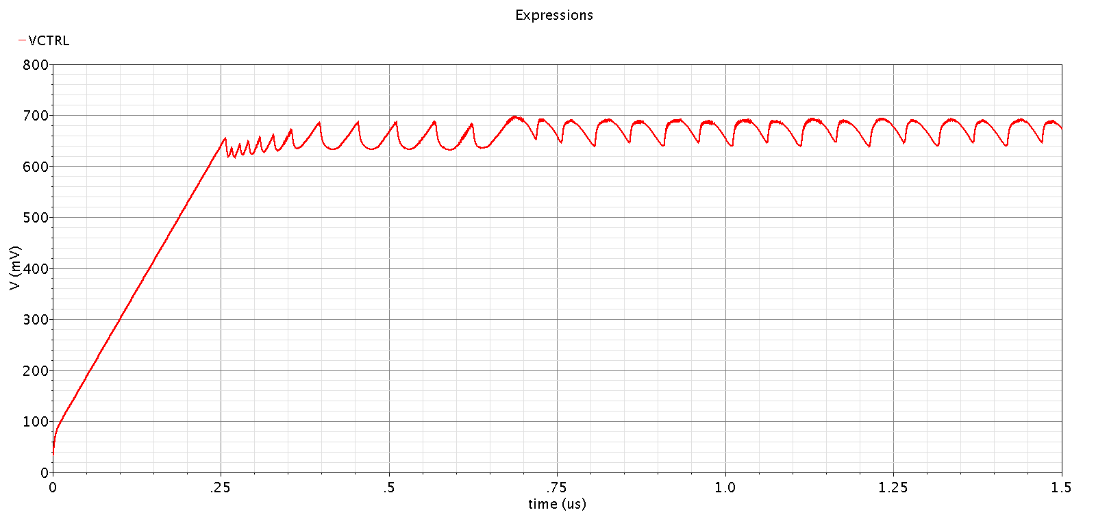
When I went to Cadence transistor-level simulation, I could always see when the control voltage approaches the voltage required for locking (close to 0.7V in my case), it always has a low frequency ripple on it. I've attached the settling behavior of the control voltage. The ripple is about 18MHz and has a peak-peak amplitude of about 40mV.
I've tried to replace the VCO with an ideal VCO and the loop locked quietly with only high frequency ripple (frequency same as my reference) of about 1mV, so I assume the problem comes from my VCO. But my VCO works good individually as a block with a good linearity in the range of interest. I also tried to add two vcvs as buffers before and after the VCO in the PLL, but that didn't help.
I don't quite understand where the low frequency (18MHz) ripple comes from and how to solve the problem. I will appreciate if you can give any inputs or suggestions!
Faye
Here is the settling behavior of the PLL control voltage: