Continue to Site

Welcome to EDAboard.com

Welcome to our site! EDAboard.com is an international Electronics Discussion Forum focused on EDA software, circuits, schematics, books, theory, papers, asic, pld, 8051, DSP, Network, RF, Analog Design, PCB, Service Manuals... and a whole lot more! To participate you need to register. Registration is free. Click here to register now.

Low duty cycle Buck?

cupoftea

Advanced Member level 5
Joined
Jun 13, 2021
Messages
2,589
Helped
54
Reputation
108
Reaction score
115
Trophy points
63
Activity points
13,604
Hi,
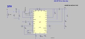
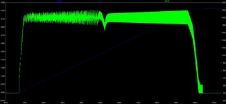
We are doing a Buck supercap charger, repeatedly charging 25F from 0 to 6V, from 37Vin.
Obviously, the Buck controller should ideally work in constant off time mode till the supercap gets above 1V, otherwise the duty cycle , and on_time , is ridiculously small.
But there is nothing on the market for this application. The best we can find is the LM5117 which uses ECM, so can at least handle low on times without spurious turning off from the switch-on spike.

Why is this application so underserved?

LM5117
 
Hi,
The bizarre thing is, that the LT8391 Buck controller does this repeated supercap charger job perfectly...on the LTspice simulator.
The LT8391 , whose frequency is set for a fixed 300khz, somehow, magically opererates with a frequency of just 50kHz, when the supercap voltage is near zero, and then magically, gradually increases its switching frequency as the supercap voltage gradually rises
LT calls this pulse-skip operation. Other manufacturers do the same thing. It's not very novel.

If it weren't for such features, then these circuits would struggle to regulate the output without a minimum load.
 
Big on specs??
size? cost/W? footprint?efficiency? parts count?

30A Magnetics are likely the driver for cost for this 120W battery charger or else two 100A FETs
 
Last edited:
A standard CMOS buck or psu control chip with a very slow soft start ( large SS cap ) will allow very small duty cycle into what is effectively a short circuit at start up.

Even the common garden UC3856 allows duty cycles as low as 200nS, and allows driving 2 low side fets at up to 47% each of the period.

This chip would suffice and would spread the switching load over 2 fets

If the fets are placed in the high side - an high side driver chip would need to be interposed.
 
Thanks, ayk, the problem is that when on_time is so short, the actual gate drive pulse can trigger the current mode switch off......also, the turn on spike...this is why the LM5117 was invented......i believe we must use it.....or some microcontrol solution whereby a buck switchs for 3 or so cycles, then stops to allow the current to fall back, then another three or so, etc etc...until the supercap voltage gets up to some sensible voltage where the on time is long enough.

The other way for us is to use a "starter buck", which literally has a sense resistor downstream of the inductor...which, at first , is essentially grounded as the output is zero volts for ages......this "starter buck" then switches out once vout gets off the floor....then the LT8391, or whatever , takes over.
 
Last edited:
Are there resonant or hysteretic square pulse converters with
current mode control? Those are fixed on time, whatever off
time it takes. But I have seen (for lack of looking) nothing about
current mode control (that would not be per-pulse, since those
styles want to control pulse for other things, but "quick
enough" average)?

Or, use a voltage mode buck but make the feedback "compound"
with (say) current-sense being the feedback quantity, until charge
voltage is exceeded, and then quit altogether?

Now that (and the idea that this is for some bank-scale testing,
maybe suggests that you want a master and a rack of slave
current sources (sinks too?) with each of those having some
charge-termination ability / monitor? Figuring on-time is current
and average that out, can you get "good enough" balance
between channels and bang them "dumb, but safe"?

Of course I'd bet that an off-the-shelf and no farting around in
the lab for a week, is more the plan.
 
I think Easy Peasy is right.....we must use UCXXXX type, since the forced LEB time of all the modern pwm controllers means you get staircasing.
 
Hi,
The bizarre thing is, that the LT8391 Buck controller does this repeated supercap charger job perfectly...on the LTspice simulator.
The LT8391 , whose frequency is set for a fixed 300khz, somehow, magically opererates with a frequency of just 50kHz, when the supercap voltage is near zero, and then magically, gradually increases its switching frequency as the supercap voltage gradually rises......i mean.........great!...thats exactly the behaviour we want........but does the real LT8391 do this?......the LT8391 datasheet says nothing about this switching frequency changing capability.

Shall we lay it out on the PCB and just prey that the switching frequency change fairies come to our aid?....just like they did in the LTspice simulator?

LT8391
 

Attachments

  • LT8391 supercap charger.jpg
    LT8391 supercap charger.jpg
    116.9 KB · Views: 70
  • LT8391 supercap charger_WAVEFORMS.jpg
    LT8391 supercap charger_WAVEFORMS.jpg
    132 KB · Views: 68
  • LT8391_supercap charger.zip
    1.5 KB · Views: 62
A straightforward solution for the buck controller would be a hysteretic current controller, 20A +/- 2.5..5A. Alternatively current comparator for on threshold plus constant on time.
 
Thanks, how would you refer the current sense signal down to the comparator?
Current sense transformer?
I tend to agree with you but the solution of #10 is very low in component count. (though of course, it has only ever worked in LTspice so far)
 
Thanks, ayk, pulse skipping would tend to give you integer divisors of the switching frequency...thats not what you see in the sim of #10 above.....its a very gradual and deliberate change of switching frequency. Pulse skipping is the "gap toothing" of the switching pulses.

This gradual frequency chnage is not depicted in the LT8391 datasheet...does it happen in the real part...or is it just a sim_dream?
I ran the sim and it's definitely pulse skipping. The time between leading edges of the TG pulses is always an integer multiple of 3.3us.

It's even more obvious if you apply a clock to the sync pin. You will find that the TG pulses always line up with the clock edges.

1682424827444.png
 

LaTeX Commands Quick-Menu:

Similar threads

Part and Inventory Search

Welcome to EDABoard.com

Sponsor

Back
Top