Continue to Site

Welcome to EDAboard.com

Welcome to our site! EDAboard.com is an international Electronics Discussion Forum focused on EDA software, circuits, schematics, books, theory, papers, asic, pld, 8051, DSP, Network, RF, Analog Design, PCB, Service Manuals... and a whole lot more! To participate you need to register. Registration is free. Click here to register now.

Loop induction vs no induction

Salvador12

Full Member level 4
Joined
Jul 16, 2014
Messages
206
Helped
3
Reputation
6
Reaction score
7
Trophy points
1,298
Activity points
3,950
Hey guys, can you help me out a little here,
If what I know is true then whenever you have a coil/loop within a generator or elsewhere you only get induced current in it if the B field lines are either increasing or decreasing through it.
So if I have a loop and a magnet slides past it like the rotor magnetic poles within a generator then at any given time the loop can be crossed by just one pole or to put it otherwise field lines have to be all in one direction.

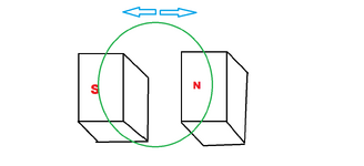
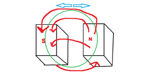
What happens if I take a loop of wire and move it back and forth over a magnetic dipole such that one side of the loop cuts say N pole surface while the other is on top of the S pole, I should get no induction , no current in the loop and therefore no opposition to the movement of the loop against the magnet correct?
Please see the attached picture.

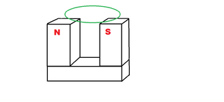
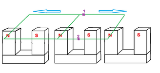
I think it is only if my loop moves further on one side or the other such that it then engulfs only one pole of the magnet with field lines going all in one direction when I start to get induced current correct?
So as long as my loop has both sides on opposing field lines there should be no induced current?
 

Attachments

  • loop.png
    loop.png
    24.5 KB · Views: 77
Variation of magnetic flux through a conductor loop induces a voltage in the first place. It may also involve a current in connected circuit.

Direction of magnetic field in your sketch isn't clearly enough defined to determine if loop movement involves a flux variation and respective induced voltage. I guess yes, because field of one pole increases and of the other pole decreases during movement.
 
if the magnetic flux is changing, there is an induced EMF, and if there is a path for the current, an induced current and an induced magnetic field.

if i read your drawing correctly, when the loop is evenly spaced between the N and S poles, there can be zero net flux
but the net flux isn't the issue. the change in flux is
 
Direction of magnetic field in your sketch isn't clearly enough defined to determine if loop movement involves a flux variation and respective induced voltage.
I edited the attached picture, imagine you are looking at the top of the magnet pole pair and the loop is moving across it, the red lines represent the field lines.


if i read your drawing correctly, when the loop is evenly spaced between the N and S poles, there can be zero net flux
but the net flux isn't the issue. the change in flux is
The total flux stays the same because both poles have 1/2 of the flux and the loop is moving across the pole surfaces, so as it leaves one pole less of it's field lines penetrate the loop while more of the field lines from the other pole penetrate the loop and vice versa, the total flux density stays the same but as you mentioned the field lines change direction so the flux density stays the same I think overall but the flux changes direction gradually if the loop ismoved in one or the other direction.
So for every one field line in one direction that leaves the loop, another field line of the opposite direction enters it.

I am not sure whether this leads to induction, remember that the loop never enters an area where it engulfs only a single pole because field lines in single direction increasing/decreasing surely lead to induction as that is how almost every generator works.
But what happens when the loop moves such that both sides of it are always across opposite poles of the magnet?

My first thought is that if for every field line in one direction that leaves another one in the opposite direction is added then the total change of flux is zero even though field lines swap direction but my thinking is that to get induction field lines must swap direction all together not one by one because that should lead to no induction because you always get opposing force?

I am thinking of the classical experiment where you take an axially magnetized cylindrical magnet and pass it down through the Z axis of a solenoid coil, you get induction but that is because the coil is cut first by field lines all in one direction and then all in the other one, but what would happen if you took that same magnet and flipped it sideways with it's opposing poles facing the inside face of the coil and then passed it through, I think there would be no induction
--- Updated ---

PS. I am not sure about one other thing, if there indeed is current in the loop in the described situation of it moving across a magnetic dipole, whether it would be because of what @wwfeldman said about flux direction change despite total flux being the same or whether it would be due to Lorentz force on each half of the loop where one half would experience a bottom up current if moved from left to right for example and the other part a top down one.
 

Attachments

  • loop.png
    loop.png
    30.1 KB · Views: 62
Last edited:
your drawings have some issues:
magnets only come as N and S pole pairs.
You show a N pole and S pole
the magnetic field lines originate on N poles and end on S poles, so the arrow from S to N is incorrect

try drawing the drawing from the front view instead of the top view.

magnetic field is a vector
magnetic flux is the scalar product of the magnetic field vector and the area vector
the area vector's magnitude is the area of the loop
the area vector's direction is perpendicular to the plane of the loop

for argument's sake, the area vector points in the same direction as the magnetic field lines leaving the north pole of the magnet.
that means that the flux due to the north pole is positive and the flux due to the south pole is negative

when the loop is completely over the north pole, the the flux is positive
as it moves toward the south pole, the flux changes toward the negative
until the loop is entirely over the south pole, hence the flux changes with time
and it continues to change when you move the loop back toward the N pole
 
As @wwfeldman requested here is a side view of the idea at hand.
Now even if @FvM is correct in his doubling down on "there will be induced voltage" I am not sure whether it would be for the reasons suspected.
Allow me to explain, take the core on any common apparatus that works on the principle of induction whether it be the core through each of the windings on a synchronous generator or a transformer. - the flux changes but always you have field lines in one direction as it does.
For example in a transformer, first you get an increase in flux then a decrease then it falls to zero and reverses direction, never can you get flux in opposite directions through a core , am I right?

So for a loop like this that crosses both directions of flux at the same time, I would believe that if any induced current occurs it would be solely due to Lorentz force because the loop moves in the same direction at once, with reversing field directions one part of the loop would get current deflected in one way while the other in the other way.
I do not see how classical induction - the change of flux through an area with respect to time could get induction here because for every one field line exiting the loop another one with the opposite direction enters it, the total flux stays the same simply the direction gets reverses but not all at once but "slowly" field line by filed line.
 

Attachments

  • loop.png
    loop.png
    22.3 KB · Views: 62
As stated "field of one pole increases and of the other pole decreases during movement." You are not looking for number of field lines (static field) but for the variation.
 
For a simplified analysis, assume constant and perpendicular field over the pole pieces. A1 and A2 being the partial pole piece surface areas covered by the loop. Total flux through the loop is thus F = A1*B - A2*B, induced voltage V = dF/dt = B*d(A1-A2)/dt. Even if A1 = A2 (loop centered over the pole pieces), dA1/dt and dA2/dt have opposite sign when the loop is moved in N-S direction.
 
lets make your loop rectangular - this view is easier for me

as you say, by the Lorentz Force, (magnetic part), F = qvB
then the left side, over the S pole, gets an induced EMF one way,
and the right side, over the N pole, gets an induced EMF the other way
the other two sides do not induce any EMF

since these two EMFs are in opposite direction, there may be a net EMF

note however, that the magnitude of the EMFs change as the B field changes.
then there may be an net EMF, and hence a current and an induced magnetic field.

this works for any shape loop - the math is relatively easy for a rectangular loop,
a bit harder for a circular loop, and a bit harder for an arbitrarily shaped loop

the use of Faraday's Law that FvM and I have been trying to explain is not
separate from Lorentz's Law, nor are they mutually exclusive.

the use of one or the other depends on the situation.
pick one, and solve the problem
pick the other, and solve the problem
both should yield the same results.

in this case, Faraday's Law is easier to apply, as it only depends on the
area of the loop, not the shape of the loop
 
Ok, maybe indeed I have made a mistake in my reasoning and it could very well be that also in a practical generator as the rotor field turns around, a coil that the field passes experiences both one way flux at the same time as the reverse flux starts entering the coils in the moment when the previous pole turns away from the coil and the next pole is already entering the loop area of the coil.

If my goal was to shield a loop passing by magnetic poles from induced current , how would I do it? Given I cannot use any extra layers of conductive material but just the loop itself, would a simple "8" twist be enough?
Like if the geometry is perfectly symmetrical both for the loop and the magnetic poles, does then creating an "8" or similar current canceling geometry does indeed cancel any net current that would otherwise be induced and therefore also cancel any back EMF that would try to oppose the movement of the said coil/loop?
 
@FvM @wwfeldman so i thought about it and came up with an interesting albeit most likely not new solution/example.

In the image below attached, the blue arrows show the direction of the loop that it can travel in , lets just assume we have a line of magnet pole pairs.
In my previous example I had just a single loop represented by a green rectangle or circle.
As this loop moved across the pole pairs the flux direction changed gradually every time the sides of the loop(that cover over the magnet poles) left their respective similar pole pairs to move onto opposite direction/polarity pole pairs which as we concluded resulted in current generated in the loop.

But what if in the line of magnet pole pairs I connect multiple similar loops all in parallel, because current in each loop when all of them go in the same direction is also in the same direction , therefore any net current in each loop should cancel with the one in the next as they share a common side, and should result in no net current induced?

The tricky part here is this - given the loops are positioned such that all sides at any given time only cross like polarity poles do I still get magnetic current deflection aka Lorentz Force with the resulting voltage difference developed across the sides of the loop that do not cover the poles meanwhile get no current induction from flux change as said loop traverses the pole pairs?

The Lorentz Force deflection voltage points are labeled violet and have numbers (1;2)
 

Attachments

  • loop1.png
    loop1.png
    27.7 KB · Views: 62
If my goal was to shield a loop passing by magnetic poles from induced current , how would I do it?
Yes, if the field is periodical, you can ideally cancel induced voltage (and also any magnetic force on the coil) by making the coil length equal to period. As suggested in your latest post.
 

LaTeX Commands Quick-Menu:

Similar threads

Part and Inventory Search

Welcome to EDABoard.com

Sponsor

Back
Top