blueroomelectronics
Advanced Member level 5
- Joined
- Sep 17, 2006
- Messages
- 1,681
- Helped
- 180
- Reputation
- 358
- Reaction score
- 77
- Trophy points
- 1,328
- Location
- Toronto, Canada
- Activity points
- 8,696
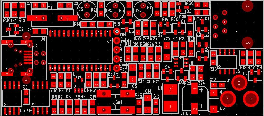
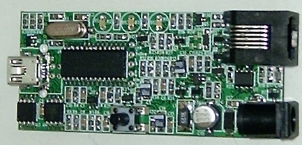
Schematics for ICD2
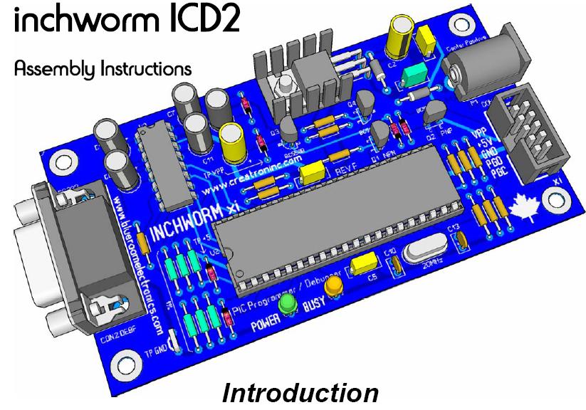
The free Google Sketchup is quite a tool. Tons of free drawings too on google. Don't give up, it took me a couple of weeks to learn but I'm still working on the mastery. The video tutorials will help you. Practice and you can do something like this.
**broken link removed**
The free Google Sketchup is quite a tool. Tons of free drawings too on google. Don't give up, it took me a couple of weeks to learn but I'm still working on the mastery. The video tutorials will help you. Practice and you can do something like this.
**broken link removed**
")