Continue to Site

Welcome to EDAboard.com

Welcome to our site! EDAboard.com is an international Electronics Discussion Forum focused on EDA software, circuits, schematics, books, theory, papers, asic, pld, 8051, DSP, Network, RF, Analog Design, PCB, Service Manuals... and a whole lot more! To participate you need to register. Registration is free. Click here to register now.

Looking for a 2.4 GHz patch antenna

Status
Not open for further replies.

JoeDreck

Newbie level 4
Joined
Aug 8, 2012
Messages
6
Helped
0
Reputation
0
Reaction score
0
Trophy points
1,281
Activity points
1,318
Hello,

i am looking for an antenna which is working with a ground plane on the bottom side of the substrate (FR4) at 2.4GHz.

It will be placed on "biological objects" like human beeings. What is important for the right antenna in this case?

I found four similar patch antennas:

  • Circular inset-fed linear polarised patch
  • Rectangular inset-fed linear patch
  • Circular Edge-fed linear polarised patch
  • Rectangular Edge-fed Patch


Circular_edge-fed_linearly_polarised_patch-antenna_design.pngCircular_inset-fed_linearly_polarised_patch-antenna_design.pngRectangular_edge-fed_patch-antenna_design.pngRectangular_inset-fed_microstrip_patch-antenna_design.png


I think the performance should be very similar?

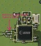
I what to use this antenna with a TI/Chipcon ZigBee Transceiver and a balun (75Ω to 50Ω), could i now leave out the fed lines to the antenna. Or in other words: Is the fed line for matching only?

Thanks.
 
Last edited:

Re: 2.4 GHz Patch Antenna

The thin (non 50 Ohms) feed lines are part of the matching, so they cannot be removed, unless you design your own matching network. The 50 Ohms lines can be removed, shorted or extended. Based on width of trace, height and relative epsilon, you can determine the characteristic impedance of the transmission lines.

Given same size of ground plane, all these antennas will have similar performance (so I agree with your statement).
 
Re: 2.4 GHz Patch Antenna

Actually I will use an own matching network (look at the attached picture).

So I can connect the antenna directly after the matching network?
 

Attachments

  • cc2420.jpg
    cc2420.jpg
    41.6 KB · Views: 98

Re: 2.4 GHz Patch Antenna

Your matching network transforms to 50 Ohms unbalanced, so you should not remove the non 50 Ohms transmission line sections from the antenna.

When you would connect your chip + matching directly to the edge of a half wave resonating patch, you will have significant mismatch. The input impedance at the edge of a half wave resonating patch antenna is much higher then 50 Ohms.

Other thing: if you are using an existing proven antenna design, make sure to keep the distance between ground plane and patch the same. You may know that there is relatively large spread in relative epsilon for FR4 (unless you use material with controlled er). This may lead to some performance degradation due to change in the antenna's center frequency
 
Re: 2.4 GHz Patch Antenna

OK, thank you Wim.

So i could use the "inset-fed" antennas, because the matching is created with the help of the inset, is that right?

I want to keep the design as small as possible.
 

Re: 2.4 GHz Patch Antenna

Can you explain your project more clearly? You want to put a 2.4GHz antenna and circuits in the human body? That doesn't make sense.
 

Re: 2.4 GHz Patch Antenna

I want to use it with a 3D acceleration sensor for tracking the movement and send it to computer for example.
 

Status
Not open for further replies.

Part and Inventory Search

Welcome to EDABoard.com

Sponsor

Back
Top