Continue to Site

Welcome to EDAboard.com

Welcome to our site! EDAboard.com is an international Electronics Discussion Forum focused on EDA software, circuits, schematics, books, theory, papers, asic, pld, 8051, DSP, Network, RF, Analog Design, PCB, Service Manuals... and a whole lot more! To participate you need to register. Registration is free. Click here to register now.

Load sharing Boost SMPS's swap the load repeatedly

Status
Not open for further replies.

cupoftea

Advanced Member level 5
Joined
Jun 13, 2021
Messages
2,589
Helped
54
Reputation
108
Reaction score
115
Trophy points
63
Activity points
13,602
Hi,
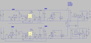
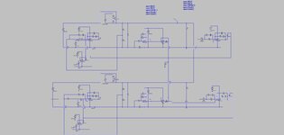
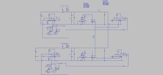
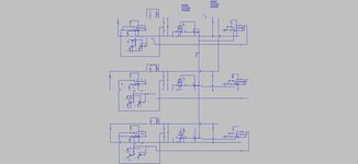
The attached shows load sharing boost converters. Though, Instead of sharing simultaneously, they swap the load between themselves repeatedly.
Do you know how to solve this?
Should one converter "always" be the master, instead of as shown, where either can be master.
(LTspice and jpeg attached)

The operation just passes the amplified output current sense value to the joint "share" bus, and each converter trys to get equal to that in its current delivery (kind of like the UC3902 does it)
 

Attachments

  • Parallel boosts load sharing.jpg
    Parallel boosts load sharing.jpg
    186.5 KB · Views: 116
  • Parallel Boost with Load share.zip
    4.6 KB · Views: 106

Thanks yes, it could be done that way....but we wish to do it like the UC3902 does it.....so as to reap the benefits of that method.
 

You say you want to copy UC3902 load share controller operation mode, but you apparently don't understand it's prerequisites. It's manipulating voltage sense in front of the individual PI controllers with a correction signal, which as far as I see doesn't happen in your design.

The UC3902 approach is necessary if you don't have access to the voltage controller manipulated value, e.g. when using POL modules without dedicated tracking feature. Your switcher has this feature already by exposing the comp node and evenmore your circuit by using an external voltage controller.

Parallel operation of PI voltage controllers without sense signal manipulations will make the integrators run to the limits.
 

It's manipulating voltage sense in front of the individual PI controllers with a correction signal, which as far as I see doesn't happen in your design.
...In the UC3902 App Note examples, the UC3902 does indeed operate exactly as you say...however, AYK, it can also be set up to act on the reference voltage of each error amplifier of each power stage.
I appreciate the example i give in top post is a little contrived, but i still wish to make it load share as per the "UC3902 method".
Also, i wish to also re-do it to act with the remote feedback resistor, as you kindly imply.

Its this "UC3902 principle" of having the sensed & amplified output current as a "share bus"...and then making all paralleled "independent" SMPS's share by using that.......when the simulation is going well, we will be more into the method....and then be able to adapt it to a 50kW SMPS that we wish for, by using multiple paralelled modules.

The UC3902 is a little baffling, as it appears that any of the paralleled SMPS's can be the master, and they can all adjust their reference voltage....which seems a bit precarious, as surely at least one fixed reference voltage is required, to stop the vout drifting too far from the required nominal value?
 

After reviewing the schematic again, I realize that you have correction signals to the voltage controller inputs. Problem may be that you have two integrators although there should be only one balancing signal (overdetermination). So yes, it can be done similarly, but probably no exactly this way.
 
EDIT...the attached works quite well, settling out after a while quite equally...but i forgot to connect up the top current equalisation error amp properly...so it works, but is wrongly connected up ....END OF EDIT

Yes, i think the integrator that deals with equalising the currents should be of a bandwidth some 10x lower than the actual regulation error amps....but the sim takes ages to run if you do like that.
The attached is doing it with linear regs in pllel, so the sim runs a bit quicker. There are two 50mV voltage sources that are needed to make it work (V10 and V16)....i think these are to make sure that the SMPS that first becomes "master"...then stays as "master. But im not so sure yet what these voltages do.

I think that it relys on one of them becoming "master", and then staying as master.....otherwise, if the master changes, then it becomes chaotic and vout suffers disturbances.

Such a voltage source exists in UC3902...and im guessing that this is its purpose...ie, to "secure the master as master"?

It seems a strange thing that the system doesnt know who is master till it starts up......but it must work out who's master very quickly, otherwise it cant work.

The sizing of the 50mV voltage source seems to depend on the current sense resistor max voltage and the volt drop to th eload along the circuit conductors......if too much current trace resistance is there, then the UC3902 method literally doesnt work it seems?....or it needs the 50mV volt source to be increased?

LTspice and jpeg as attached
 

Attachments

  • Linreg with load share.jpg
    Linreg with load share.jpg
    127.2 KB · Views: 106
  • Linreg with Load share.zip
    4 KB · Views: 89
Last edited:

Aaaah....the attached (LTspice and jpeg) appears to have cracked it.....the secret was just to limit the range of voltages to the error amp ref.
So would you say the attached is the best way to do it?

If not limited, then they both just drag the refs down to min.
--- Updated ---

Also it is seen working (sharing) with three in pllel "x3".....each of the triplet has a different divider resistor..yet they still share...would you say this is the de facto method?
Can you improve it..?..and why are the 50mV sources needed?

And is there any way of reducing the component count?
 

Attachments

  • Linreg with Load share_works.zip
    4.5 KB · Views: 91
  • Linreg with load share_works.jpg
    Linreg with load share_works.jpg
    125.3 KB · Views: 87
  • Linreg with load share_works x3.jpg
    Linreg with load share_works x3.jpg
    116.1 KB · Views: 90
  • Linreg with Load share_works x3.zip
    6.4 KB · Views: 88
Last edited:

Status
Not open for further replies.

Similar threads

Part and Inventory Search

Welcome to EDABoard.com

Sponsor

Back
Top