Continue to Site

Welcome to EDAboard.com

Welcome to our site! EDAboard.com is an international Electronics Discussion Forum focused on EDA software, circuits, schematics, books, theory, papers, asic, pld, 8051, DSP, Network, RF, Analog Design, PCB, Service Manuals... and a whole lot more! To participate you need to register. Registration is free. Click here to register now.

LMX2541 pll/vco combo - how to modulate?

Status
Not open for further replies.
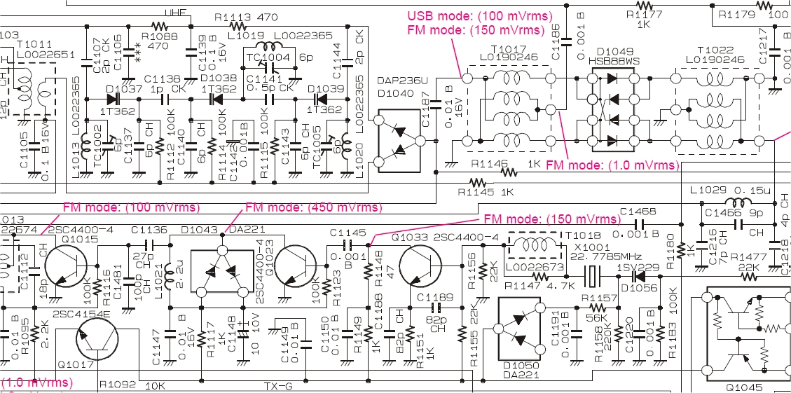
FT-817 (as most of Japanese transceivers) use a discrete stage for FM modulator.
In this case FM modulator is Q1033 using a 22.7785MHz crystal (R1183 and R1477 setting the frequency deviation), and few multipliers followed by the RF channel mixer.


I don't understand what you mean, my understanding is that the resulting modulation coming from the pll unit would be as analog as any other fm and it wouldn't be visible to the "outside world" that it has been generated this way. Furthermore, why would channel bandwidth need to be huge?

No doubt there are more sophisticated ways than this. I just pulled the manual of the FT817 and had a look at the pll unit - this one is brilliant but hey, they even had a custom pll chip made! It's a question of expense and return - I was looking for a multi-band design that is as simple as possible but still good enough for jazz (I mean fm). I'm not very confident that vcos built with discrete components will work good enough and the ready-made ones do often not cover the frequencies needed and are expensive as well.

Maybe I'm missing something but biff44 was suggesting a digital audio mode to replace the analogue FM. If you want to send enough information by FSK to be able to rebuild human speech at the other end then you will need loads of bandwidth to support the bit rate. If the data was sent uncompressed it would need about a 500kHz bandwidth just to send basic quality audio.


If the FT817 uses a VCXO to generate FM and these radios sound OK then why not copy their circuit and run it at 20MHz and use it as your reference and use this to generate FM using my alternative approach?

If I've missed the point of biff44's FSK method then maybe he or you could explain what he really meant?
 

I had another think about biff44's method.

Did he mean that the FSK pin would be 'dithered' at a very high rate to produce analogue audio at the VCO due to the VCO integrating the audio from the dither? I'd imagine the FSK pin would have to be dithered at an extremely high rate.

Was that the idea? It's an interesting idea but I can't say how practical it would be?

I'm still unsure about this method but it is interesting.
 
Last edited:

I am not sure how well this would work, but you could take your voice source, lowpass filter it at 3 KHz, and then run it into a 1-bit ADC at a 6 KHz clock rate. You would use that 1 bit to modulate the PLL digital divsor using the "data" pin on that chip. You would need the PLL loop bandwidth to be perhaps 20 KHz, which is easily do-able.

At the other end, you would demodlate the signal as a 0 or 1, and then lowpass filter it again with a 3 KHz filter to turn it back to an analog signal, amplify, and there you go!

1 bit analog to digital converters were popular a decade ago....but they still live on in effect in class D amplifers, etc, which are "1-bit" analog devices.
 

Status
Not open for further replies.

Part and Inventory Search

Welcome to EDABoard.com

Sponsor

Back
Top