Continue to Site

Welcome to EDAboard.com

Welcome to our site! EDAboard.com is an international Electronics Discussion Forum focused on EDA software, circuits, schematics, books, theory, papers, asic, pld, 8051, DSP, Network, RF, Analog Design, PCB, Service Manuals... and a whole lot more! To participate you need to register. Registration is free. Click here to register now.

LM723 Regulated Ac to Dc from 3-30V Troubleshooting

Status
Not open for further replies.

Jukac

Newbie level 4
Joined
Apr 27, 2011
Messages
6
Helped
0
Reputation
0
Reaction score
0
Trophy points
1,281
Activity points
1,325
First off all excuse my bad English.

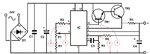
I am makeing an regulated power supply from 3-30V dc i made the PCB based on this design 3-30 V/2.5 A Stabilized power supply . On the output i put a LED and a 2k resistor which glow with a constant brightnes regardles how I change the ristence via the potenciometer the only diference that i made is the potenciometer it is a 1k ohms and should be 10k, but i dont think that is the problem causing the supply to have an constant output. The capacitor C2 with 2200uF does look a litlle strange althouh it is new it is a litle swalen an the ruber side (axial capacitor).
Thank you in advance :smile:
 

Assuming that there are no mistakes in the PCB, soldering, components, etc, etc, measure voltage on the 723's following pins:
[4]=in(+)
[5]=in(-)
[6]=Vref
and
[10]=out
and report ..

IanP
:wink:
 
  • Like
Reactions: Jukac

    Jukac

    Points: 2
    Helpful Answer Positive Rating
stupid question but just to make sure because i dont have a voltmeter at home, i measure it between the pins and the negativ out?
Thank you for your patience :)
 

In this circuit, the reference is (-) rail .. see attached picture ..

IanP
:wink:
 

Attachments

  • 732-PS1.JPG
    732-PS1.JPG
    57.3 KB · Views: 182
  • Like
Reactions: Jukac

    Jukac

    Points: 2
    Helpful Answer Positive Rating
so the voltages are as follows:
(4) = 0,1V
(5) = 1V
(6) = 1V
(10) = 1,5V

there shoold be more at pin 4 shouldnt there :s
 

Pin [6] is the reference voltage and should read exactly 7.15V (see data sheet), as long as the Vcc is roughly >=12Vdc ..
Disconnect potentiometer and external transistors and check the unregulated supply voltage, pin [12] ..
If the voltage on pin [12] is above 12Vdc measure voltage on pin [6] ..
It must read 7.15V ..
If it doesn't the IC may be damaged ..


https://focus.ti.com/lit/ds/symlink/ua723.pdf

IanP
:wink:
 
  • Like
Reactions: Jukac

    Jukac

    Points: 2
    Helpful Answer Positive Rating
The voltage on pin (12) is 34,5V and pin (6) has a constant 1V. When i was measuring this i didnt have any output voltage, but when posting the thread i had so my guess is that i blew the IC :/
When i was makeing the PCB i didnt mirror the picture of the conections on the card so I couldnt use a normal LM723D i had to use one in the H or TO01 caseing. I think my best option would be makeing a new PCB so i can insert the standard cheap one. This project is getting rather costly :/

Thank you for your help :)
 

Hi its me again :)
I am going to make a new pcb tommorrow and I was wondering if I had blown the IC there should be a mistake in the schematic, so if you can notice anything irregular just say it or even if you have a schematic for another power supply for up to 30V regulated at 2A i would be realy thankfull :)
 

I remember experimenting with LM723 eons ago, its a finicky piece, and your asking for trouble without a resistor in the base lead of
the transistor, or Vz/Vout pin

just check what the spec says about the drive ability of that pin/chip, and take a look at the internal diagram of the chip.
The chip doesn't have any internal limiting ability, you need to design for it.
It does have an excellent temperature compensated reference though!

and yes your above results indicates dead chip, easy to do with this one i'm afraid.

LM723 is an old design, must have been one of the first voltage reg chips designed/manufactured...........
 
Last edited:
  • Like
Reactions: Jukac

    V

    Points: 2
    Helpful Answer Positive Rating

    Jukac

    Points: 2
    Helpful Answer Positive Rating
i was looking into the design and noticed the previous one had cardial mistakes, based on the pdf file that IanP gave a link to.
so now im going to make a new design but i have a few questiones i attached a picture the one on the left is the original one but if i want to make the output voltage to be regulated i need to add a pot and im wondering did I make it right on the right picture, and should i remove R1 and R2 if add the pot or not and how big should the pot be and the resistors R1 and R2 or how do i calculate them based on the desired voltage which should be roughly 4-30V dc
 

Attachments

  • maturalni.gif
    maturalni.gif
    27.2 KB · Views: 96
Last edited:

Status
Not open for further replies.

Part and Inventory Search

Welcome to EDABoard.com

Sponsor

Back
Top