tms8c8
Newbie level 4

- Joined
- Dec 3, 2014
- Messages
- 7
- Helped
- 0
- Reputation
- 0
- Reaction score
- 0
- Trophy points
- 1
- Activity points
- 91
I am building some digital electronics for an industrial application and there is one part that I would like to replace but I am struggling with the design. I will attach the schematic of my initial concept. I tried simulating it and ran into some unexpected behavior. The breadboard version worked for awhile but then I fried something. Let me explain the application first:
There is a legacy piece of custom industrial equipment that has an indicator bulb. It normally has a high impedance voltage output and then switches to a low impedance output to drive a 25W light bulb. Basically, there is always 28 VDC going to the light bulb but normally there is a resistor in series with the bulb, which limits the current such that the bulb is not on. The purpose of this is to detect a burnt-out bulb. That circuitry is essentially "sealed" but seems to require a test current of about 50 mA for the equipment to continue running. Some quick tests suggest that the maximum input impedance of my circuit must be less than 50 ohms in order to allow the required test current to flow (i.e. the output impedance is about 510 ohms).
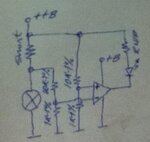
My initial thought was to use an LM393 comparator and a current sense resistor. To prevent dissipating a continuous 15-25 watts at the board, I thought I was real clever using the comparators, a current sense resistor, an RC time delay and a MOSFET. But it doesn't seem to work as I expected. Anyone see the (probably obvious) flaw in my concept?
How I thought it would work:
Current flows from pin 2 on U8 into the node at R17 and R18. R17 is the current sense resistor (I was planning on using some 3W 10 ohm resistors because I need them elsewhere on the board).
When the bulb is on, the voltage across R17 increases above the threshold and the comparator triggers, pulling the output low. This results in the MOSFET turning off so there is only a brief, large current pulse through the resistor.
However, when the MOSFET is off, the voltage at R17(2) will go to 28V, so I put a zener in there to protect the comparator. Now the input voltage is at the zener voltage, which is still above the threshold so the "trigger" never resets.
But hey... a 393 has two comparators so I thought I'd use a slow RC ramp on one input and the reference on the other input. When the first comparator goes low, it also starts discharging the RC circuit and at some point it will trigger, pulling the input of the other comparator low, which in turn lets that comparator's output go high, resetting the circuit.

There is a legacy piece of custom industrial equipment that has an indicator bulb. It normally has a high impedance voltage output and then switches to a low impedance output to drive a 25W light bulb. Basically, there is always 28 VDC going to the light bulb but normally there is a resistor in series with the bulb, which limits the current such that the bulb is not on. The purpose of this is to detect a burnt-out bulb. That circuitry is essentially "sealed" but seems to require a test current of about 50 mA for the equipment to continue running. Some quick tests suggest that the maximum input impedance of my circuit must be less than 50 ohms in order to allow the required test current to flow (i.e. the output impedance is about 510 ohms).
My initial thought was to use an LM393 comparator and a current sense resistor. To prevent dissipating a continuous 15-25 watts at the board, I thought I was real clever using the comparators, a current sense resistor, an RC time delay and a MOSFET. But it doesn't seem to work as I expected. Anyone see the (probably obvious) flaw in my concept?
How I thought it would work:
Current flows from pin 2 on U8 into the node at R17 and R18. R17 is the current sense resistor (I was planning on using some 3W 10 ohm resistors because I need them elsewhere on the board).
When the bulb is on, the voltage across R17 increases above the threshold and the comparator triggers, pulling the output low. This results in the MOSFET turning off so there is only a brief, large current pulse through the resistor.
However, when the MOSFET is off, the voltage at R17(2) will go to 28V, so I put a zener in there to protect the comparator. Now the input voltage is at the zener voltage, which is still above the threshold so the "trigger" never resets.
But hey... a 393 has two comparators so I thought I'd use a slow RC ramp on one input and the reference on the other input. When the first comparator goes low, it also starts discharging the RC circuit and at some point it will trigger, pulling the input of the other comparator low, which in turn lets that comparator's output go high, resetting the circuit.