leaualorin
Junior Member level 1
Hello everybody and thank you for existing(you and the internet!  ).
).
I recently been "busy" building voltage regulators using LM338K , LM317T and finally LM350 for charging A123 SYSTEMS LiFePo4 (lithium phosphate) batteries!
The first project was with a LM338K wich "died suddenly" to my GIGANTIC dissapointment...
I never find out the "causes" , although it worked just fine until I hooked up a 55/60W halogen car light bulb wich SHOULD HAVE BEEN in its limits(4,6Amps).
Anyway:
The LM317T is still working but I want to charge these batteries to the specifications that the manufacturer provides (3Amps for normal charging or 10Amps for fast charging).
The circuit with the LM350 caught fire when I hooked up a circuit wich I had no ideea of how much amps draws and it did draw "ABOUT 6,5 AMPS" this being the result for the potentiometer to catch fire and the LM350 to make a "sinister pop"...
I have 4 more LM350 IC and I want to make 1 or 2 chargers and be able to charge the batteries at minimum 3 amps and be able to set the voltage at 3,55 volts on a multimeter before actually charging the batteries!
I gave up the 10 amp charger with 3 LM350 and a LM307 because I simply can't find a LM307 or LM308 IC and the 4,5 volts minimum voltage(I need maximum 3,55 volts for charging these batteries) ...
SO :
I want some advices regarding the well-building of a battery charger with the adjustable voltage and a 3 amp constant and non-variable charging curent!
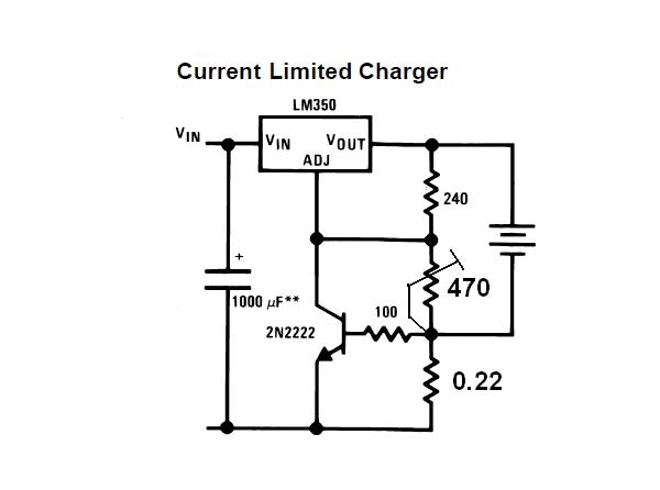
I searched thoroughly in the datasheet for LM150/LM350A/LM350 and there are 2 schematics that have "drawn my attention":
one is for a 3amp constant curent at page 10/14 in the bottom wich seems preety much "bullet proof" with no potentiometer to "cache fire" :roll: in case of some stupidity from my part and another schematic would be a "combination" betwen the one at the top of the page 6 and the one at top of the page 7 WITH the output capacitors in!
The big dillema is how would I hook these schematic( 3amp curent regulator and the adjustable voltage regulator) without everything ending up in smoke and "strange smell" AGAIN!
Thank you kindly and I hope someone can help me (if it wants) with some good advices regarding this adjustable supply!
Good day!

).I recently been "busy" building voltage regulators using LM338K , LM317T and finally LM350 for charging A123 SYSTEMS LiFePo4 (lithium phosphate) batteries!
The first project was with a LM338K wich "died suddenly" to my GIGANTIC dissapointment...
I never find out the "causes" , although it worked just fine until I hooked up a 55/60W halogen car light bulb wich SHOULD HAVE BEEN in its limits(4,6Amps).
Anyway:
The LM317T is still working but I want to charge these batteries to the specifications that the manufacturer provides (3Amps for normal charging or 10Amps for fast charging).
The circuit with the LM350 caught fire when I hooked up a circuit wich I had no ideea of how much amps draws and it did draw "ABOUT 6,5 AMPS" this being the result for the potentiometer to catch fire and the LM350 to make a "sinister pop"...
I have 4 more LM350 IC and I want to make 1 or 2 chargers and be able to charge the batteries at minimum 3 amps and be able to set the voltage at 3,55 volts on a multimeter before actually charging the batteries!
I gave up the 10 amp charger with 3 LM350 and a LM307 because I simply can't find a LM307 or LM308 IC and the 4,5 volts minimum voltage(I need maximum 3,55 volts for charging these batteries) ...
SO :
I want some advices regarding the well-building of a battery charger with the adjustable voltage and a 3 amp constant and non-variable charging curent!
I searched thoroughly in the datasheet for LM150/LM350A/LM350 and there are 2 schematics that have "drawn my attention":
one is for a 3amp constant curent at page 10/14 in the bottom wich seems preety much "bullet proof" with no potentiometer to "cache fire" :roll: in case of some stupidity from my part and another schematic would be a "combination" betwen the one at the top of the page 6 and the one at top of the page 7 WITH the output capacitors in!
The big dillema is how would I hook these schematic( 3amp curent regulator and the adjustable voltage regulator) without everything ending up in smoke and "strange smell" AGAIN!
Thank you kindly and I hope someone can help me (if it wants) with some good advices regarding this adjustable supply!
Good day!
Last edited: