Continue to Site

Welcome to EDAboard.com

Welcome to our site! EDAboard.com is an international Electronics Discussion Forum focused on EDA software, circuits, schematics, books, theory, papers, asic, pld, 8051, DSP, Network, RF, Analog Design, PCB, Service Manuals... and a whole lot more! To participate you need to register. Registration is free. Click here to register now.

LM350 led driver, LED brightness control.

Status
Not open for further replies.

zoulzubazz

Member level 5
Member level 5
Joined
Apr 26, 2012
Messages
87
Helped
3
Reputation
6
Reaction score
3
Trophy points
1,288
Visit site
Activity points
2,040
hello everyone,

The idea is to drive power LED's with an LM350 used as a constant current source as shown in the following scheme

https://www.onsemi.com/pub_link/Collateral/AND8109-D.PDF

Now, the LED's can be dimmed by varying the resistor (R) between OUT and ADJ pin of the regulator. But the requirement is to control the birghtness of the LED's using a 0 - 1V DC signal coming from a potentiometer, could this done using a transistor or a FET connected with R to vary current between 350mA to 1A?

Thanks.
 

Hi,

this is a high side current source. It regulates so that between OUT and ADJ is 1.25V.
For a good regulation you can use a open collector current source to Gnd, that is controlled by your 0..1V signal.( simple Opamp circuit)
Now put a second resistor in the line to ADJ.
Also connect the open collector to the ADJ pin.

What values to use:
Lets assume that the current source regulates 0..10mA with 0..1V input.
This means you need a 100 Ohms resistor at the emitter.
The usual current setup resister should be used to supply 1A. This means 1.25 Ohms.
The additional resistor is: (1.25V - 0.35A * 1.25 Ohms) / 10mA = 81.25 Ohms.
Now with 0 V you get 1A, and linearely decreasing to 350 mA with 1V.

Hope this helps.
Klaus
 
hey Klaus, thanks very much for your reply, but i am unable to gather the circuit described. would you kindly be able to pencil draw a rough diagram of your description in order to obtain a better idea. Thanks very much.
 

Hi

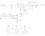
here my schematic

sch1sw.jpg

Klaus
 
hey thank you very much klaus, much appretiated. Now, my circuit analysis skills are very bad so please correct me if i am wrong,
when (1) is zero the BJT does not conduct hence (2) is zero therefore (3) is 1.25/[81+1.25] = 15mA and so on. is this the right way to look at this?
Thanks.
 

Hi,

it´s like thinking round the corner....

The opamp circuit with the transistor forma an adjustable constant current source.
With 0...1V at (1) and You can now adjust the currrent at (2) linearely to 0..10 mA. This is fix.

No we don´t care about the 50..10uA current of the adj-pin of the LM350. We calculate it as 0 uA.

So all the currrent of our current source is going through the 81 ohms causing a voltage drop of 0...10mA x 81 ohms = 0 ....0.81 V

The LM350 regulates in a way that the voltage drop from its output to its adj to be 1.25V.
With the voltage drop on the 81 ohms there is a voltage drop of 1.25V - (0 ... 0.81 V) = 1.25V ... 0.44V on the 1.25 ohms resistor.
1.25V @ 1.25 ohms are 1.0 A (LED max);
0.44V @ 1.25 ohms are 0.35 A (LED min).

That´s it

Good luck
 
Status
Not open for further replies.

Similar threads

Part and Inventory Search

Welcome to EDABoard.com

Sponsor

Back
Top