Continue to Site
Follow along with the video below to see how to install our site as a web app on your home screen.
Note: This feature may not be available in some browsers.
#include"lpc214x.h"
#include<stdio.h>


#define LED (0x00000001<<7)
#define BIT16 (0X00000001<<16)
#define BIT18 (0X00000001<<18)
#define BIT24 (0X00000001<<24)  //po.28 adc0.1

 unsigned char key_press[]="key press";
void PrintonVGA(unsigned char *);
void adc_init(void);
void UART_Init (void);
void adc_read(void);
int main()
{
unsigned int i;
UART_Init() ;
PINSEL1=BIT24; //ADC0.1

IODIR0=LED;
IODIR0|=~KEY;
adc_init();

PrintonVGA( key_press);
adc_read();
IOSET0=LED;
for(i=0;i<40000;i++);
IOCLR0=LED;


void adc_read(void)
{

	float res=0;
unsigned char buf[20];
AD0CR|=0X01000000;
PrintonVGA(" Start conversion");
while(!(AD0DR1 & 0x80000000)); // checking for done bit
PrintonVGA("converted");

res=((AD0DR1>>6)&(0x000003ff)); // extracting the converted value


	sprintf(buf,"%f",res);
PrintonVGA(buf);
AD0CR|=0x00200302; // stop adc

}
void adc_init(void)
{
        PCONP |= 0x0100;

	AD0CR=0x00200302;  //channel 1 adc 0 pclk=15mHz/4
}

void UART_Init (void)
{

  PINSEL0 |= BIT16 + BIT18;


  U1LCR = 0x83;
  U1DLM = 0x00;
  U1DLL = 0x62;
  U1LCR = 0x03;


  U1FCR = 0x07;
}


void SendUARTByte (int ch)
{
  while (!(U1LSR & 0x20));
  U1THR = ch;
}

void PrintonVGA(unsigned char *ptrBuf)
{

  while(*ptrBuf != '\0')
  {
    SendUARTByte(*ptrBuf);
    ptrBuf++;
  }
}hello,
Are sure about the wiring ?
With a potentiometer your voltage input is 0 to 5V , isn't it ?
with LM35 you only can get 250mV @ 25°C ..
what is the analog input range 0-5V 0-1023 pts
( i don't know your µP.)
Even with a low level input you must get any points of measure ( 50 pts )
hello,
if it's works with a potentiometer 0 to 3,3V
it must work with the LM35
did you get 0 to 1023 pts with the potar 0 to 100% ?
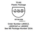
what LM35 packaging do you have?
joined doc for TO92 BOTTOM VIEW !
can you measure LM35 output with a multimeter ?
res=(float) AD0DR1; // extracting the converted [B]RAW value[/B]
sprintf(buf,"%f",res);ok have changed it,using unsigned int to extract the value(raw value) into. it's reading full value 1023.I am a bit suprised for using a long to get ADC value ( 10 bits ADC , so normal int 16 bits is enough))
Try to printout intermediate result
Code:res=(float) AD0DR1; // extracting the converted [B]RAW value[/B] sprintf(buf,"%f",res);
There is no while(1) loop in your code. Try giving a rewference voltage of 1.7V to the ADC. Does the adc input pin have any other multiplexed functions? See if you have to configure any register to make the adc input pin for analog operation.
The values are changing between 0 - 1023 for the potentiometer. it reads 500 something or 800 something etc. I am shifting by 6 because in the addr register the data is available after conversion from 6th bit to 15th bit.Remember i don't know your µP..
but on microchip we decide if the ADC measure is left or right justified (for MSB and LSB byte)
ie: for right justified
we add LSB + MSB <<8 to obtain a word ( unsigned int) with the 10 bits value inside it.
or you divide by 64 ( >>6) i don't know why, but i suppose the probleme is around this.
what do you get with potentiometer and RAW value
and turn slowly potentiometer to see if you get every value between 0 and 1023 ..
i don't think so you could..
int main()
{
unsigned int i;
UART_Init() ;
PINSEL1=BIT24; //ADC0.1

[B][COLOR="#FF0000"]do
{[/COLOR][/B]

IODIR0=LED;
IODIR0|=~KEY;
adc_init();

PrintonVGA( key_press);
adc_read();
IOSET0=LED;
for(i=0;i<40000;i++);
IOCLR0=LED;


[B][COLOR="#FF0000"]} while (1);[/COLOR][/B]
[B]}[/B]hello,
Where is the closing parenthesis in the main function ?
Code:int main() { unsigned int i; UART_Init() ; PINSEL1=BIT24; //ADC0.1 [B][COLOR="#FF0000"]do {[/COLOR][/B] IODIR0=LED; IODIR0|=~KEY; adc_init(); PrintonVGA( key_press); adc_read(); IOSET0=LED; for(i=0;i<40000;i++); IOCLR0=LED; [B][COLOR="#FF0000"]} while (1);[/COLOR][/B] [B]}[/B]