Continue to Site

Welcome to EDAboard.com

Welcome to our site! EDAboard.com is an international Electronics Discussion Forum focused on EDA software, circuits, schematics, books, theory, papers, asic, pld, 8051, DSP, Network, RF, Analog Design, PCB, Service Manuals... and a whole lot more! To participate you need to register. Registration is free. Click here to register now.

LM339 comparator problem

Status
Not open for further replies.

sangeo

Member level 2
Joined
Jun 2, 2013
Messages
44
Helped
0
Reputation
0
Reaction score
0
Trophy points
1,286
Activity points
1,647
Haii all I am facing a with a problem in my comparator design ,I designed, simulated the same in proteus and it works well. But when I practically designed the circuit there is always a 0.5 volt difference showing triggering ie when –ve input set to 1.5 volt , then 2v in +ve terminal required to trigger the op amp. What will be the reason ..Its output offset voltage also 0.5v,Idont know offset voltage have any role in this problem. If anybody knows the reason please help ,if any additional circuitry required please provide that one also.
Thanks
Saneesh George
 

Hi,

i´m sure this is not caused by the LM339. Most likely it is caused by your circuit, wiring or measurement.

Without your schematic and a detailed description we have to guess.

Klaus
 

There is no "output offset voltage". There is the Vce(sat)
of the output transistor under load, and that's it.

At the input it sounds like your circuit has hysteresis,
no LM339 will ship with 500mV Vio. An inspection of the
schematic would show whether hysteresis is to be
expected.
 

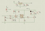
Actually i forgot to attach the schematic here i attached the schematic.Her i am feeding 4-20 ma through A1 and A2, and inverting terminal is feeding with Vref, But 0.5 volt more than Vref required to change opamp output. I think output voltage may be vce saturation voltage but what will be the difference in triggering voltages at input


schemattic.jpg
 
Last edited:

You did not read the datasheet for the LM339. Its minimum output current is only 4mA to 6mA but since you have its load resistor value too low at 1k ohms then with the 12V supply you are trying to get 12mA from it.
Its output current is low because it is "Low Power".

Are you using the optocoupler to try to boost the current from the comparator? You do not say its part number for us to see if its "minimum current transfer ratio" is more than 1.
 

Hi,

...another example why a schematic is so important for us to help....

******
There are some issues and confusions...
Audioguru is correct with output current. 6mA is the minimum value given in the datasheet. The typical of 16mA is more relaxed. This may be a problem, but i don´t see this as the main problem.

In my opinion there is a problem with wiring and/or power supply.

Do some tests:
Connect the "minus" of a DVM to the GND pin of the 7812 and leave it there for all further voltage measurements (just to have a fixed point to rely on)
Now adjust pot so that the relay just is NOT switched ON. Please note all the voltage measurements (maybe on the schematic paper)
* measure GND leg of R4
* measure VCC leg of RV2
* Measure Pin3 of LM339
* Measure Pin7 of LM339
* Measure Pin6 of LM339
* Measure Pin1 of LM339
* Measure GND leg of RV2
Now adjust pot so that the relay switches ON, then back so it just is NOT switches OFF.
Please measure all the voltages like before and note it (with another color )

In my eyes two problems can cause your problem:
* either it is the power supply that drops voltage when relay is swtiched ON,
* or a wiring problem causes to raise GND voltage on R4.

**************
Althoug there are no errors in ourircuit, i have some suggestions.
* As audioguru mentioned: there is no need for an optocoupler.
* I personally don´t like the connection of R6, U1 and U2. The voltage on U1-pin1 may change from 1.3V when relay is ON, to 0.3V when relay is OFF. R6 is always powered.
* And i´d more like R7 on the right side of R9.

hope that helps

Klaus
 

With an output current low of only 6mA, some LM339 ICs will have a horrible maximum saturation voltage of 1.5V that certainly will not turn off the optocoupler or transistor.
 

Thanks Mr.Audio guru and Mr KlausST .Finally i solved the problem but still i don't know how its happens.Actually i used a pot of 1M ohm instead of 33k in circuit, I replaced the 1M ohm by a 10k pot then it is working exactly. I checked with all 4 cooperators of 339 and all works well. I think Mr.Audio guru and Mr KlausST you will get the exact reason behind this problem now because you have well experience in this field. If you understood the problem please explain for me.

Regard
 

The pot was fed directly from the 12V unregulated power supply. When the relay was powered then the 12V probably dropped which also dropped the reference voltage to the comparator.he maximum input current of an LM339 comparator is 0.25uA and must be fed from a low voltage or ground because the inputs have PNP transistors. Maybe you had the 1M pot connected as a rheostat instead of as a voltage divider but now the 10k pot is a voltage divider.

EDIT: The tiny little letters on the schematic showing a regulator might say, "12V" so the regulator will not regulate with an input of only 12V. A 12V regulator needs a minimum input of 14.5V.
 
  • Like
Reactions: sangeo

    sangeo

    Points: 2
    Helpful Answer Positive Rating
Hi,

In my eyes two problems can cause your problem:
* either it is the power supply that drops voltage when relay is swtiched ON,
* or a wiring problem causes to raise GND voltage on R4.

Too lazy to do the measurements?

Klaus
 
  • Like
Reactions: sangeo

    sangeo

    Points: 2
    Helpful Answer Positive Rating
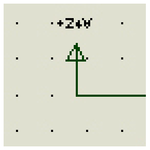
My eyes have trouble seeing the tiny letters on that (Multisim?) schematic covered with dots and a colored background. The input to the LM7812 regulator looks like +Z4H which might be 24V?
The pot is fed from +12u which might be +12V but the output of the regulator is called POWER, not 12V.

Another problem with the schematic is that it was saved as a fuzzy Jpeg file type instead of as a very clear PNG file type.
 

Attachments

  • fuzzy Jpeg image.png
    fuzzy Jpeg image.png
    7 KB · Views: 59
  • Like
Reactions: sangeo

    sangeo

    Points: 2
    Helpful Answer Positive Rating
Ok thanks for your Time and consideration,both of you helped me a lot
 

Status
Not open for further replies.

Similar threads

Part and Inventory Search

Welcome to EDABoard.com

Sponsor

Back
Top