Continue to Site

Welcome to EDAboard.com

Welcome to our site! EDAboard.com is an international Electronics Discussion Forum focused on EDA software, circuits, schematics, books, theory, papers, asic, pld, 8051, DSP, Network, RF, Analog Design, PCB, Service Manuals... and a whole lot more! To participate you need to register. Registration is free. Click here to register now.

LM338 15A Power Supply Circuit - HELP please

Status
Not open for further replies.

3BABY

Member level 5
Member level 5
Joined
Jan 14, 2011
Messages
91
Helped
0
Reputation
0
Reaction score
0
Trophy points
1,286
Location
New Zealand
Visit site
Activity points
2,252
Hi All,

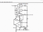
i have the below circuit, straight out of he Texas LM338 datasheet as a reference circuit, i would like to use it to build a 15-20A 8v power supply, what i dont understand from the circuit is the resistors R5 and R6 being 0.1 Ohm each. i understand that for 15A the circuit uses all 3 LM338's specified at max 5A output, but what i dont understand is why the resistors are there (R5, R6) ? more i dont understand what rating they will have to be. the biggest i can find is around 3W.. if my basic calculations are correct 5A*8V = 40W.. isnt this going to blow R5, R6 straight out of the circuit?? your help please for my understanding would muchly appreciated

also note: i have found replacement for the LM307 as Analog Devices OP177.. as LM307 is not longer available.

Thanks!

u51z.jpg
 
Last edited by a moderator:

R5 and R6 are there to equalize or ballance currents flowing out from above two regulators. Power rating for those two resistors and R2 is 5A*5A*0.1=2.5W~3W. R1 must be 10A*10A*0.05=5W which you can make paralleling two 0.1 ohm/3W resistors. OP177 is wrong choice because it's vorking positive input voltage is less than positive supply voltage (Vsup=+-15V, IVR=+-13V...+-14V). It will not work. Search for input rail to rail OPA.
 

R5 and R6 are there to equalize or ballance currents flowing out from above two regulators. Power rating for those two resistors and R2 is 5A*5A*0.1=2.5W~3W. R1 must be 10A*10A*0.05=5W which you can make paralleling two 0.1 ohm/3W resistors. OP177 is wrong choice because it's vorking positive input voltage is less than positive supply voltage (Vsup=+-15V, IVR=+-13V...+-14V). It will not work. Search for input rail to rail OPA.

Hi!! thanks for the reply, i have been looking over the datasheet and i see another circuit that looks a bit better with the use of LM741. i would still like to use it for 8V 20A supply. will the LM741 work with 8V supply?

also i dont understand the calculation. am i going to have to use a 50W .1Ohm resistor on the output side of the LM338's or would i get away with 3W? same goes for the 0.05Ohm resistor on the input. could you please elaborate on the calculation? thankyou :)

circuit below:

8pt.gif
 
Last edited by a moderator:

Max allowed current through 0.1ohm resistor is 5A and through 0.05ohm is two times bigger. Power dissipated on resistor is calculated by using Ohms Law. Both demo circuits has no overcurrent protection or current limiting and in case of short circuit on the output components will be destroyed.
I am not shure that LM741 can replace LM308 regarding circuit stability.
As I can see you are a begginer and it would be better to find schematics of working power supply instead to use demo circuits from datasheets.


Hi Borber,

thankyou for the reply! yes you are correct im fairly new to op-amps and high current power circuits using silicon and not just straight big transformers and capacitors, this is infact my first post in the Analog section on this forum. Digital electronics is where my knowledge lies. but thankyou for your help!!

ohms law would give me at 8V 8v/0.1 = 80A which is allot more than the LM338 can produce.. so no overcurrent protection. if i used 0.3ohm resistors like the below schematic link (which is also a link to a working circuit that is modification of the above using LM741 instead of LM307.) this would give me 8V/0.3 = 26.6A so again no over-current protection. for "over current" or atleast current to 5A per LM338.. i would have to use 1.6 Ohm resistors. is this correct?

my biggest concern is the power rating of the resistors. if i was to be pulling 5A from each regulator at 8V this would give me 40W of power. which means i would need a resistor equal to that or above a 40W rating.. is this a correct assumption?

please see below to a link of a very similar circuit:


https://electronics-diy.com/electronic_schematic.php?id=650


thankyou! :)
 

Wrong assumption!

You are calculating on the basis that the whole output voltage is across the resistor, in reality, the voltage dropped is proportional to the current through them into the load and the power they dissipate is I*I*R in Watts. So under no load they disspate no power at all. The danger is that these designs have no short circuit protection so if you completely shorted the output terminals the power they dissipate could be much more. In reality, if you did that the chances are something else would burn out first.

Brian.
 

Thanks!

ok so the question is, what Power rating can i use for the output resistor(s) if the resistance in 0.3-0.5 ohm?
 

Output resistor for 3xLM338 and 8V output voltage must be greater than 0.5333 ohm and must withstand max 120W. (Assumed is proper cooling for regulators. Without cooling you can get less then few watts from such supply or smoke will be rleased.)
 
Last edited:

I gave you the formula to calculate it. It is the current you pass through them squared (in Amps) multiplied by the resistance (in Ohms) and the result is in Watts.

So if the resistors are 0.3 Ohms and you draw 1A through them they dissipate 0.3 Watts and if you draw 20A through them they dissipate 120 W.
If instead they are 0.5 Ohms the figures would be 0.5W and 200W respectively.

Bear in mind that the resistors are not there to limit the output current, they are to help the regulators to share the load between them. If you leave them out altogether and one regulator tries to produce slightly more voltage than another, it will dissipate more power than the others. Typically values of 0.1 Ohms or less are used.

Always use resistors with slightly higher power rating than the worst case dissipation. Remember you can make up the values from more than one resistor too and they share the power dissipation between them.

However, the regulators themselves probably can't manage to supply that much current each anyway so in practise the circuit would fail before 20A was reached. Also bear in mind that the regulators themselves dissipate the voltage dropped across them multiplied by the current through them. You need at least 11 V in to the circuit to get 8V out (the minimum allowed for most regulators) so at 20A load they dissipate 120W themselves, you need very big heat sinks and probably forced air cooling on them.

I think you can see why commercial PSUs are so expensive and why SMPS is preferred over linear regulators when the power demand is so high.

Brian.
 

Thanks for the reply Brian,

ok so im working with a circuit with 4xLM338 with resistors values of 0.1 ohm each. this would give me a power dissipation of 2.5W when 5A is being drawn from each regulator (so i can get the full 20A - LM338 is rated for 5A) so if i choose a 0.1 ohm cement resistor with 5W rating this should be ok?

i have an input voltage of 12V @ 25A available. this should be sufficient?

also if i work in an short circuit protection, could i just add 1N4004 between input and output of the regulators?

thanks for your help! i really appreciate it! :)
 

A unique feature of the LM138 family is time-dependent
current limiting. The current limit circuitry allows peak currents
of up to 12A to be drawn from the regulator for short
periods of time. This allows the LM138 to be used with heavy
transient loads and speeds start-up under full-load conditions.
Under sustained loading conditions, the current limit
decreases to a safe value protecting the regulator. Also
included on the chip are thermal overload protection and
safe area protection for the power transistor. Overload protection
remains functional even if the adjustment pin is accidentally
disconnected.

This is straight from the data sheet. Protection is built into this regulator :)
 

There are no timer circuits inside an LM138/338, the limit quoted is only for a few mS and is thermally controlled.

3BABY, yes that would work for the regulators and resistors but the short circuit protection idea is completely wrong. Adding a diode 'backwards' between the input and output is a good idea because it protects the circuit if the output voltage is higher than the input voltage. This situation can arise at the time you switch the AC supply off and when for example you are charging a battery which holds the output voltage up even when the input is disconnected.

Short circuit protection works in a different way, it monitors the output current and drops the voltage, if it becomes excessive. The voltage will of course drop if you overload the output anyway but the idea of the limiter circuit is it does it under better control and well before the components are pushed beyond their limits.

Brian.
 

resistors values of 0.1 ohm each. this would give me a power dissipation of 2.5W when 5A is being drawn from each regulator

see this is the part that is confusing me. if the above statement is correct i have 8V at 5A going through a 0.1 ohm resistor. using P=V*I this give me 40W. but the question is.. we have 40W of power being used by "the load" doesnt that mean that the resistor should have a power rating of 40W to handle the 5A at 8V thats going through it? or am i looking at this wrong.. the resistor isnt using any power.. so its not using any of the 40W, the load is using the 40W. now im just getting confused

if i use the equation I = sqrt(P/R) for the 5W 0.1ohm resistor i get a maximum safe current of 7.07A so the 0.1ohm 5W resistor can handle up to 7.07A. which is ok. but im still confused why we are applying an equation of P = I^2 * R for the resistor minimum safe power rating, and not P= V*I ?

thanks!!
 

..but im still confused why we are applying an equation of P = I^2 * R for the resistor minimum safe power rating, and not P= V*I ?
Resistors are characterized by their resistance and max power.
That is enough to calculate max current and max voltage drop (in case you need to know it for something).
You can apply voltage-current formula, V*I, and then replace V[voltage] by R*I, and that leaves you with I*I*R - back to square one.
:wink:
IanP
 

Status
Not open for further replies.

Similar threads

Part and Inventory Search

Welcome to EDABoard.com

Sponsor

Back
Top