Continue to Site

Welcome to EDAboard.com

Welcome to our site! EDAboard.com is an international Electronics Discussion Forum focused on EDA software, circuits, schematics, books, theory, papers, asic, pld, 8051, DSP, Network, RF, Analog Design, PCB, Service Manuals... and a whole lot more! To participate you need to register. Registration is free. Click here to register now.

[SOLVED] LM2576 is driving me crazy (V drops when load added)

Status
Not open for further replies.

baby_2

Advanced Member level 4
Joined
Jul 20, 2016
Messages
105
Helped
2
Reputation
4
Reaction score
1
Trophy points
18
Activity points
873
Hi,
I want to get a 5volt 1A with using Lm2756-5V. I assembled a circuit according to datasheet schematic.
Capture.PNG
I use:
input voltage 30volt
SS34 as D1
470uf Cap
inductor 100uH(with 1.6A)

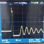
But I can't get more than 200mA, and When I attach a load to output of LM2576 it voltage drops less than 4 volt.I change Capacitor to 2200uf and inductor 220uH (with 2A) and also I have added a Diode(1N4007) as you can see in blue but it dosen't work well.
when I drive output with a 10ohm resistor to get .5A output my LM2576 burns suddenly and it's output get equal value to it's input voltage.( I have burned 6 Lm2576 with different components)

what is my mistake? ( I have bought different kind of LM2576 (Onsemi , National semiconductor))
 

Waveforms.
Please show us the waveforms at pin 2 at:
min load, and max load.

Are you by any chance assembling this circuit on a protoboard?
 
  • Like
Reactions: baby_2

    baby_2

    Points: 2
    Helpful Answer Positive Rating
Hi,

It could be many things, and above request makes sense, more so than guessing, however...
After checking that it isn't likely to be overstepping junction temperature, in fact it seems 0.5A doesn't even need a heat sink if all that generates in PD is 0.45W... The OnSemi datasheet has inductor values for the fixed 5V version,the charts on pages 13 and 14 seem to say that the inductor should be at least 470uH and more the 680uH (H680 code) for a 30V input and 0.5A out.

Aside, copying the "typical application" schematics that appear at the beginning of a datasheet is - in my own experience - often - but not always - not a good idea, they tend to represent the general concept of the component more than a fully usable circuit.
 
  • Like
Reactions: baby_2

    baby_2

    Points: 2
    Helpful Answer Positive Rating
Thanks for your contribution
without any loads:(vout=5volt)
1.jpg
2.jpg
but when I have attached a 20ohm load it passed away and I see a flat line on my oscope and Vout=30 volt. I have tested them on the breadboard
 

Attachments

  • 1.jpg
    1.jpg
    385.7 KB · Views: 116

What type of layout are you using?
Is there a good ground plane?
The circuit likely won't work properly if it's on a plug-in type breadboard.
 
  • Like
Reactions: baby_2

    baby_2

    Points: 2
    Helpful Answer Positive Rating
Thanks crustchow for your response.
I have bought (To-220 CASE 314D) that I can insert easily into breadboard.my ground wire is a wire that can withstand more than 2.5A. However , I think for more than .5A to 1A my ground wire and breadboard strip are enough.
 

Hi,

A breadboard is not suitable to test power switching circuits.
There is a big difference if there is 2.5A DC current or 2.5A RMS switching current.

Klaus
 
  • Like
Reactions: baby_2

    baby_2

    Points: 2
    Helpful Answer Positive Rating
Thanks crustchow for your response.
I have bought (To-220 CASE 314D) that I can insert easily into breadboard.my ground wire is a wire that can withstand more than 2.5A. However , I think for more than .5A to 1A my ground wire and breadboard strip are enough.
I'm not concerted about whether the ground wire can withstand the current.
If all the ground connections are not to a low impedance ground plane, the circuit will likely not work properly.
A plug-in breadboard has way too much stray capacitance and inductance to be used with a switching power supply.

You likely won't get the circuit to work correctly unless you put it on a vector-type perf board with a copper ground plane, and good bypass capacitors directly from the power pins to the ground plane.

Otherwise you are likely just spinning your wheels. :bang:
 
  • Like
Reactions: baby_2

    baby_2

    Points: 2
    Helpful Answer Positive Rating
The regulator senses this voltage drop and tries to compensate as I understand.Breadboard cannot carry high currents and GND connections must be tightly done to the IC.Weak connections will disturb its operation.
 

If I was given one dollar for every forum poster who made a higher frequency circuit that doesn't work because it was built on a solderless breadboard then I would be a millionaire.
 

Thanks all for your contributions and explanations.
The d123 user tip works fine and my problem has been gone by using the proper inductor according to input/output voltage and current.
Thanks for all of you that you mentioned breadboard's characteristic that I haven't paid attention to it before. because I think the low freq about 50khz and a short length track doesn't have much effect on my circuit .
 

    raman00084

    Points: 2
    Helpful Answer Positive Rating
Dear crustschow
You are my teachers and thank you for sharing your wisdom with me. I mean I thought That it is correct. it is possible to introduce me some new adjustable switching regulators (Something like lm2576)that can withstand input voltage between (12-40)Volt and output current approximate 2A with less value of inductor(100uH to 220uH)? because I want to use smd components and I need small size of inductor?
 

Hi,

simple answer:
Use the switch moder regulator manufacturer´s internet pages.
They usually have interactive selection guides.

Or use selection gudes provided by distributors.

Btw: Smaller inductance is only possible with higher switching frequency.
Then even more the PCB layout becomes important.
You need to strictely follow the design considerations given in the datasheet.

Klaus
 
  • Like
Reactions: baby_2

    baby_2

    Points: 2
    Helpful Answer Positive Rating
A switching power supply switches its pass transistor with a squarewave that has harmonics at least 15 times higher than its fundamental frequency. If its fundamental frequency was a sinewave with no harmonics then it would get very hot and waste a lot of input power making heat. Since your fundamental frequency is 50kHz then the pcb must be designed for up to 50kHz x 15= 750kHz that is in the AM radio broadcast band.
 
  • Like
Reactions: baby_2

    baby_2

    Points: 2
    Helpful Answer Positive Rating
Status
Not open for further replies.

Part and Inventory Search

Welcome to EDABoard.com

Sponsor

Back
Top