Continue to Site

Welcome to EDAboard.com

Welcome to our site! EDAboard.com is an international Electronics Discussion Forum focused on EDA software, circuits, schematics, books, theory, papers, asic, pld, 8051, DSP, Network, RF, Analog Design, PCB, Service Manuals... and a whole lot more! To participate you need to register. Registration is free. Click here to register now.

lm2576-15 inductor selection guide

Status
Not open for further replies.

abc_de

Full Member level 5
Joined
Jan 9, 2014
Messages
243
Helped
11
Reputation
22
Reaction score
11
Trophy points
1,298
Location
Ludhiana ਪੰਜਾਬ
Activity points
2,939
hello
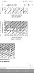
i have to use lm2576-15 switching regulator my input voltage is 33vdc and load current is 1 amp. i am bit confused about inductor. in datasheet curves its i think 100uH.
please suggest me.
 

Hi,

in the datasheet there is a design "Precedure". Follow chapter "4. Inductor selection"

Klaus
 

I read this and make calculation Its E x T =157 thus it becomes H470uH
Please let me correct if I am wrong
 

Hi,

You wrote "LM2576-15" this is a 15V fixed voltage type.
But you used the "adjustable" design precedure.

Klaus
 

The slope of your inductor current will shoot up. This means that the power supply operation, if intended to run in CCM can cross the boundary into DCM, so you may have regulation issues. Higher inductor current ripple means higher output voltage ripple for the same output filter.

Follow recommendations, unless you're testing something.
 

    abc_de

    Points: 2
    Helpful Answer Positive Rating
I have no experience that's way question is silly.
So time due to availability of inductor in local market I was asking for inductor


Up to 22v input if I use 100uH inductor then can regulator manage up to 1-3amps
Please suggest me
 

Generally, for swithhing supplies, the higher the required maximum load current, the lower the inductance needed.
--- Updated ---

The current limit spread is just very wide. Calculations for the inductor would have to be done for the two extremes, with the maximum limit being 7.5A resulting to the lowest inductance.
 
Last edited:

    abc_de

    Points: 2
    Helpful Answer Positive Rating
I understand bit not like mature
--- Updated ---

I just want to know if Choose 100uH coil then even my load is 400mA or 1.5A or inbetween this range and input voltage is 22v.
Does everything work fine ?
--- Updated ---

I just want to know if Choose 100uH coil then even my load is 400mA or 1.5A or inbetween this range and input voltage is 22v.
Does everything work fine ?
 

Attachments

  • Screenshot_20201016-221054_Drive.jpg
    Screenshot_20201016-221054_Drive.jpg
    491.8 KB · Views: 124

For your requirement at a 100uH inductor, the peak inductor current is 3.79A.

With the example given in the ONsemi data sheet, with 100uH inductor, the peak inductor current is 3.32A

The peak inductor current for the ONSemi datasheet example is below the minimum value of the current 3.5A but your is above.

At Tj = 25degC, the minimum current limit is 4.2A and is above the peak inductor current of your design.

It's worth giving a try.
--- Updated ---

Based on the chart however, you should be considering the 220uH to 330uH range.
 
Last edited:

    abc_de

    Points: 2
    Helpful Answer Positive Rating
It will work - but you may not get full current from the device - depending on heatsinking ... also more ripple in the o/p cap, amps and volts ...

the ripple for 33Vin/15Vout and 100uH is ~ +/- 1A, you say you need 1A load out so the pk I will be ~ 2.A assuming CCM ...
--- Updated ---

1602907297830.png


from the coilcraft site
1602907297660.png
1602907297830.png
1602907297660.png
 
Last edited:

    abc_de

    Points: 2
    Helpful Answer Positive Rating
The slope of your inductor current will shoot up. This means that the power supply operation, if intended to run in CCM can cross the boundary into DCM, so you may have regulation issues. Higher inductor current ripple means higher output voltage ripple for the same output filter.

Follow recommendations, unless you're testing something.

Now I understand i have to choose inductor as per input voltage and load current.

As per chart if my load is less or more then as per inductor selection then switching regulator will work in DCM.

For better performance and reliability I have to choose inductor as per load current.

One more thing lm2576 series minimum load current is .3 amps. In case if I have only .1Amp then device will work in DCM mode.

Does I am correct
--- Updated ---

I case my full load current is approximately .950Amp when board working. Suddenly due to emergency signal only microcontroller and seven segment is glowing then at that time current is less then .1Amp.
What will happen I choose inductor for 1Amps but now current is only .1Amp

Please suggest me
 
Last edited:

Now I understand i have to choose inductor as per input voltage and load current.

As per chart if my load is less or more then as per inductor selection then switching regulator will work in DCM.

For better performance and reliability I have to choose inductor as per load current.

One more thing lm2576 series minimum load current is .3 amps. In case if I have only .1Amp then device will work in DCM mode.

Does I am correct
--- Updated ---

I case my full load current is approximately .950Amp when board working. Suddenly due to emergency signal only microcontroller and seven segment is glowing then at that time current is less then .1Amp.
What will happen I choose inductor for 1Amps but now current is only .1Amp

Please suggest me

I can't say what will happen at such low current. You can easily test that without any harm when your regulator is up and running.

If it ceases to function properly at that test then I might just tell you to be a little loose with efficiency and connect a resistor in parallel with the LEDs such that the resistor always draw 200mA or a little higher at your output voltage. So as a matter of fact, select an inductor to accommodate this extra current at full load.
 

Ok that's good idea I was thinking too
I will make dummy load so that under standby condition it can draw at least .3Amp

I will test and update on post.
 

The min load current is zero for the LM2576 - where did you read it was other?
 

No that is not what that section is talking about. That section is referring to the valley of inductor current ripple and not the average value. The average value is your load current.

Although the minimum load current may not be zero as there is a lot of factors that contribute to how low duty cycle can be and still be acceptable, it is not stated that it is 300mA like you said earlier.

You should bench-test your regulator for reliability at your expected minimum load.
 

it does not state the min load is 300mA, this reg is fine for zero load.
 

Status
Not open for further replies.

Part and Inventory Search

Welcome to EDABoard.com

Sponsor

Back
Top