Continue to Site

Welcome to EDAboard.com

Welcome to our site! EDAboard.com is an international Electronics Discussion Forum focused on EDA software, circuits, schematics, books, theory, papers, asic, pld, 8051, DSP, Network, RF, Analog Design, PCB, Service Manuals... and a whole lot more! To participate you need to register. Registration is free. Click here to register now.

LLC DESIGN

Status
Not open for further replies.

alpercimendag

Newbie
Joined
Feb 9, 2023
Messages
5
Helped
0
Reputation
0
Reaction score
1
Trophy points
1
Activity points
43
Hello,

I am trying to make open loop simulasion for a LLC circuit. I am confused at some point. I am designing my half bridge LLC converter for a specific output voltage of 12V at 250W. Then I change the load(input voltage is the same) and redo my calculation to find new switching frequency. Output voltage is not 12V but far away from it.

So, I think I do not know how to calculate new switching frequency at different laods with the same input voltage. I have read all application notes available and none helps. I need someone else's answer with previous experience of designing LLC circuit.

Thanks,
Alper
You need to do a complete LLC modelling & derive the transfer function.

You may have to calculate/define the following to begin with
1) Transformer turns ratio
2) Operating switching frequency range
3) Resonant frequency value.
4) Resonant tank parameters (Lm, Lr & Cr) etc.

If your input & output voltage is fixed, design the converter at resonant frequency, as this is the point where you would get load independent operation
 

Here is the LLC design template
Also, it is dereived from AN4151 by fairchild.
Also sim in LTspice is attached.

I designed it for you...from the equn of AN-4151, the one using complx numbers

Trade secret.....make out the vout vs frequency graph, from the equn in AN4151....then go from there, remem the effective vin is half actual vin, with an half bridge LLC,
 

Attachments

  • 400V to 12v.zip
    347 KB · Views: 127
Last edited:

LLC and 'resonant' tend to go together. When an inductor and capacitor are neighbors they have a resonant frequency.

If you speed up the switching frequency, it causes the inductor to increase in impedance. The capacitor develops lesser impedance.

And it's the other way around when you slow the switching frequency.

Thus when you change the load and/or operating frequency, it becomes hard to predict what is the resulting current flow. It's hard to predict the voltage at your load.
 

You need to do a complete LLC modelling & derive the transfer function.

You may have to calculate/define the following to begin with
1) Transformer turns ratio
2) Operating switching frequency range
3) Resonant frequency value.
4) Resonant tank parameters (Lm, Lr & Cr) etc.

If your input & output voltage is fixed, design the converter at resonant frequency, as this is the point where you would get load independent operation
I've found transformer turns ratio, Lm,Lr,Cr,Q and other parameters for my case. I have designed for Vin=28V, Vout=12V, fs=130kHz for 250W output. And the simulasion works fine for such parameters.

However, when output load is changed to 60W, I cannot get 12V output for the same switching frequency of 130kHz.

That is what I do not understand. And I do not know what the new switching frequency should be. I do not know how to calculate it.
 

Here is your solution for 60w and 250w....at 60w the frequency will be higher, as shown
 

Attachments

  • 28V to 12v_.zip
    416.2 KB · Views: 80

Here is your solution for 60w and 250w....at 60w the frequency will be higher, as shown
I have checked excell file. I cannot find two switching frequencies 122 kHz&188kHz (used for 250W&60W) anywhere in the excell file. Where should I look for frequency in the excell. I need to do it myself bcs I will examine the circuit for broad range of loads and different input voltages.

Thanks you for your time.
 

If you want it in the excel, you should put in 60W into the power cell, then you read off from the graph, the frequency where it is at 12V.......(actually do it for 13.4v because of the two diode drops).

Do you need the isolation?...just thinking because i think your spec could be met by two parallel synchronous buck converters.

Also, the LLC can be changed to be synchronous of you wish......use a split coil sec and two diodes...and make them synchronous.

Also, if isolation needed, would be better to just do a synchronous full bridge converter.....give it a current doubler output so that your secondary current goes right down.
 
Last edited:

I have checked excell file. I cannot find two switching frequencies 122 kHz&188kHz (used for 250W&60W) anywhere in the excell file. Where should I look for frequency in the excell. I need to do it myself bcs I will examine the circuit for broad range of loads and different input voltages.

Thanks you for your time.

If you want it in the excel, you should put in 60W into the power cell, then you read off from the graph, the frequency where it is at 12V.......(actually do it for 13.4v because of the two diode drops).

Do you need the isolation?...just thinking because i think your spec could be met by two parallel synchronous buck converters.

Also, the LLC can be changed to be synchronous of you wish......use a split coil sec and two diodes...and make them synchronous.

Also, if isolation needed, would be better to just do a synchronous full bridge converter.....give it a current doubler output so that your secondary current goes right down.
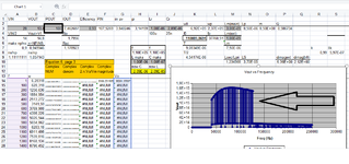
I see your point. I have changed the Pout in the excell. Then excell formulas is distorted and cant see graph anymore. I have tried it in another computer and result is the same. Do you face the same problem with the excell file?
 

Attachments

  • Untitled.png
    Untitled.png
    81.8 KB · Views: 65

Hi,
No its not distorted on my computer...here i attach it again.
Are you using excel or the free excel ? (i forget the name of the free one).

I changed the "Pout" cell to 60, and its fine, it correctly redraws the graph, so i am bemused why its going wrong for you.?

Does anybody understand how a zipped up excel file can get corrupted when its sent over the web.?
 

Attachments

  • LLC design template_checked.zip
    409.3 KB · Views: 73

Hi,
No its not distorted on my computer...here i attach it again.
Are you using excel or the free excel ? (i forget the name of the free one).

I changed the "Pout" cell to 60, and its fine, it correctly redraws the graph, so i am bemused why its going wrong for you.?

Does anybody understand how a zipped up excel file can get corrupted when its sent over the web.?
Hi, the excell file worked somehow.(ıt just started working IDK) I use excell 2016 version.
Have you realized that when dead time changes to 100ns or any other, output voltage changes significantly. It is also the case when secondary dead time changes.

I would not expect dead time to change output voltage very much bcs turn on and turn off duration of FETs are around 20ns.

Why do you think we experience this in this simulation?
 
I just ran the sim of #6 as attached, at 250w output...i changed dead time from 50ns to 100ns, to 150ns, to 200ns and it makes little difference on vout. So i am not sure to what you refer?

At 60w aswell..i changed the dead time a lot and it makes little or no difference, so i dont know what you mean?

Please ignore the secondary dead time...i have removed the secondary synchronous fets so the sec dead time wont make any difference.
 

Attachments

  • Half Bridge LLC converter_28vin 12vout 250w__230212.zip
    1.8 KB · Views: 68

Status
Not open for further replies.

Similar threads

Part and Inventory Search

Welcome to EDABoard.com

Sponsor

Back
Top