gonsays
Newbie level 5

- Joined
- Mar 25, 2015
- Messages
- 10
- Helped
- 0
- Reputation
- 0
- Reaction score
- 0
- Trophy points
- 1
- Activity points
- 83
Hello guys,
I'm new here and I'm on an introductory course to Analogic Integrated Systems.
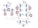
I have the following circuit of a Two-stage CMOS OTA folded cascode amplifier:

The table regarding the specifications of this circuit are the following:

------------------------------------------------------------------------------------------
As you can see on the circuit, there are two currents in black (I1 and I2). From the specifications table we know that Idd=400uA. This way we will have Idd=I1+I2.
I woul really appreaciate your help regarding the analysis or values of the dimensions for the transistors in order for this to happen.
Any help is really appreciated, because with so many specifications I don't know how to start the circuit analysis :bang:
Thank you very much in advance guys!!
Regards,
Gz
I'm new here and I'm on an introductory course to Analogic Integrated Systems.
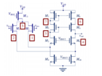
I have the following circuit of a Two-stage CMOS OTA folded cascode amplifier:

The table regarding the specifications of this circuit are the following:

------------------------------------------------------------------------------------------
As you can see on the circuit, there are two currents in black (I1 and I2). From the specifications table we know that Idd=400uA. This way we will have Idd=I1+I2.
I woul really appreaciate your help regarding the analysis or values of the dimensions for the transistors in order for this to happen.
Any help is really appreciated, because with so many specifications I don't know how to start the circuit analysis :bang:
Thank you very much in advance guys!!
Regards,
Gz


