1mace1
Newbie level 5
Hello,
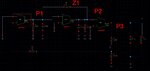
attached you see a small signal model of a linear voltage regulator with two gain stages and a source follower output stage.
From simulation I see that P2 is the dominant pole and P1 is the non dominant pole (P3 at high frequencies for small CL). But actually the miller effect should make p1 dominant and p2 non dominant or do I see something wrong? Why do I need this Miller cap here, because node P1 is low impedant and P2 high impedant?
Are these estimations correct (for p2 I am not sure)?
Z1=gm2/Cc
P1=1/(gm2R2R1Cc)
P2=(gm2Cc)/(C1C2+C2Cc+C1Cc)
that would mean that this pole is mainly dependent on C1 and C2 but I think it is mainly dependent on Cc?
P3= gm/CL
Thank you for your help