Continue to Site

Welcome to EDAboard.com

Welcome to our site! EDAboard.com is an international Electronics Discussion Forum focused on EDA software, circuits, schematics, books, theory, papers, asic, pld, 8051, DSP, Network, RF, Analog Design, PCB, Service Manuals... and a whole lot more! To participate you need to register. Registration is free. Click here to register now.

Lifetime of an over-ripple currented electrolytic capacitor?

Status
Not open for further replies.
T

treez

Guest
Hello,
My boss has asked us to design a 60W offline flyback (Vout=24V; Vin=90-265VAC).

He insists that we use the Rubycon, 120uF, 400V (18mm x 30mm) electrolytic capacitor as our primary side smoothing capacitor(datasheet and lifetime equation below).

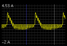
However, this capacitor is only rated for 670mA of ripple current, and in the application, at 100VAC input, the capacitor will see 1.4A of ripple current.

We have tried explaining this but he will not listen.

It is not possible for us to calculate this capacitor's lifetime with this much ripple current in it because the surface temperature rise of the capacitor goes above 20degC, and the given lifetime equation does not apply if the surface case temperature goes above 20degC.

Rubycon 120uF, 400V electrolytic capacitor.
https://www.rubycon.co.jp/en/catalog/e_pdfs/aluminum/e_kxw.pdf

Capacitor lifetime equation for rubycon 120uF, 400V capacitor:
**broken link removed**

Please find attached a representative schematic, and a LTspice simulation of the 60W flyback.

We know we should not use this capacitor, but how do we prove to our boss that we should not use it?
(The SMPS is for a shower pump, and there is some belief that we can get round the over-ripple current problem by simply controlling the SMPS to only operate say 5 minutes out of every 15 minutes)
 

Attachments

  • Flyback 60W.txt
    8.4 KB · Views: 57
  • Flyback 60W.pdf
    19.5 KB · Views: 76
Last edited by a moderator:

Your boss is an idiot, but just to check, how are you calculating temp rise with those equations? The datasheet doesn't give ESR, and the frequency of the ripple factors in as well.

If your boss won't budge then the best you can do is make the design such that it can accommodate both this capacitor and one (or more) which is properly rated, so that you can have a working design without a board revision.
 
  • Like
Reactions: treez

    T

    Points: 2
    Helpful Answer Positive Rating
If you increase the choke value (L3), it will reduce AC ripple on the 120 uF cap.

Or, put an inductor before the diode bridge. This will broaden the waveform through the bridge, so the capacitor need not endure a strong short pulse of current.

Or, if you can interleave two waveforms, it will reduce ripple. (This method may be impossible to implement in your schematic.)

No doubt your boss had to buy a lot of those capacitors in order to get a low price. That's why he insists on using them.
 
  • Like
Reactions: treez

    T

    Points: 2
    Helpful Answer Positive Rating
how are you calculating temp rise with those equations? The datasheet doesn't give ESR, and the frequency of the ripple factors in as well.

That’s a good point, because from the datasheet, the ESR can only be calculated for the case of 120Hz ripple, because tan delta is only stated for the 120Hz case.
I was intending to calculate the proportion of ripple at each of the significant frequencies, and then calculate the temperature rise due to each, and then add all the temperature rises, and use the resultant temperature rise figure in the lifetime equation. But this cannot be done because the ESR at each frequency is not known.
So I don’t really think that the lifetime calculator is all that good.

However, in any case, taking an FFT of the actual ripple in this capacitor in LTspice, shows that the vast bulk of the ripple is at 100Hz. Therefore, this points to using the ESR derived from the 120Hz tan delta figure.

And as said in the top post, the temperature rise of the capacitor is so high that the lifetime equation, as stated, is not useable.

Therefore, a lifetime cannot even be calculated for this capacitor with this overly excessive ripple current in it.
 
Last edited by a moderator:

The dissipation factor is 0.15, multiply this by the VA at 100/120 Hz to get the power dissipated, e.g. 1.4A (rms) x (141 - 100V, say 20Vpk x 0.7 = 14Vrms) = 2.94 watt.

At 3W the temp of the cap can be estimated if you know the thermal impedance. We will return to this.

From the data sheet we can have 0.67 amps rms at 105 degC (surface temp of cap) for 2000 hours life. Every 10degC you come down doubles the life, so 95=4000hrs, 85 = 8000hrs, 75=16000hrs, 65=32000hrs, 55 = 64000 hrs (7.3 years), so ideally keep cap below 55C case temp.

The surface area of the cap is pi.r^2 for the top and pi.D.h for the cylinder = 1960mm^2 (16diax35tall), to dissipate 3W in free air the temp rise will be approx 80-100 deg C (or more)
so in a 25 degC ambient the cap will be at 125deg C say.

Thus the lifetime will be 2000hrs or less (84 days) if run continuously like this.

However, caps tend to exhibit better behaviour than this initially, it will likely run a bit cooler than calculated for some time, until the electrolyte starts escaping through the seal, then the performance more quickly goes bad, the capacitance starts to drop, the power dissipated goes up and things deteriorate fairly quickly to cap failure. I would guess about a year.

Reducing the duty cycle to 5mins on, 10 mins off, extends this to 3 years which may be acceptable as it is outside warrantee(?)

Happy designing...!
 

**broken link removed**

...it is a 65W, 100-265vac offline flyback which uses a quasi resonant flyback


ST are using 1000uF from ESR= tan δ*Xc= tan δ*2πfC with DF=tan δ=0.12 for f= 120 Hz , ESR=90mΩ, yet Digi-key thinks it is 21mΩ which is not stated in the spec.

Caps rated at 25V for 19V out @ 3.42A probably getting 50% ripple current or 1.71A with cap rated at 2.36A.

There is a reason they use 3 significant figure for Amps.
No room for design slack as it can cause thermal runaway to exceed specs.

The following gives a good comparison for SMPS ESR and ripple current in an 85W 19V laptop charger.
image-jpg.92475

If you want a more reliable design specify the ESR in every component at worst case internal ambient and reduce the stress on the each part and measure peak and RMS current at max load conditions, and full step load.

Note the ratio of output current 4.2Adc to the ripple current above ( 85W 19V) and stronger consider an asymmetrical half bridge (AHB) design over the others. 0.13A rms secondary.vs 0.89 or 2.52A rms. AHB is only 2% ripple current for a resistive max load current.

But, your load is not resistive. What is the motor ESR?
 
  • Like
Reactions: treez

    T

    Points: 2
    Helpful Answer Positive Rating
Thanks, the motor ESR is 1 ohm.
We wondered if it is ok to pot smps's with electrolytic capacitors in them?...I mean, I thought electrolytics had to be able to vent their insides if they get hot, so presumably it is not acceptable to pot around electrolytics as a way of keeping them cooler running?
 

If it just to protect the electronics from the environment, use a soft potting agent, silicone rubber? This might help to conduct heat away from your capacitors. More research required!.
Frankk
 
  • Like
Reactions: treez

    T

    Points: 2
    Helpful Answer Positive Rating
Thanks, google has nothing on it, but electrolytic capacitor datasheets clearly state that they are built to allow their case to explode outwards when overheating so as to release pressure......this suggests that having them surrounded by potting compound is not allowed?

The following is from cornell dubilier, and suggests that potting around electrolytic capacitors is strictly disallowed...

Be careful not to interfere with the operation of the vent,
for instance by mounting measures such as clamps, glue or
potting compounds. In the case of large capacitors with the
capacitor elements secured by thermoplastic potting, don’t
mount them with the safety vents down as the potting may
flow when the capacitors overheat and block the vents.

http://maelabs.ucsd.edu/mae_es/partsnlinks/PopDataShts/capacitorguide.rtf
 

From the same reference as immediately above, this confirms that electrolytic capacitors should not be surrounded by potting compound...I presume you agree?

Potting and gluing
Be certain that varnishing, coating, lacquering, embedding
or gluing near the capacitors’ seals are halogen free. And
be sure all constituent parts including base material, thinners,
binders, reacting agents, propellants and additives are
halogen free. If the printed circuit board has been cleaned
with halogenated solvent, be sure it’s fully dry before
installation of capacitors. When gluing, don’t apply glue to
the full capacitor circumference, and don’t cover the capacitor’s
pressure-relief vent with potting or glue.

What a nuisance, when you get offline SMPS's at 100VAC and near 70W, the input (primary side) electrolytics tend to be under heavy ripple current, and a way of cooling them better is needed.
 

You may as well build a prototype, and find out for certain whether the capacitor will overheat. A boss doesn't want to be argued with. He's more likely to be impressed if someone shows him. At least it will tell him you believed it was possible he's right.

He probably got a promise from the sales representative, "Rubycon's reputation is tops in the industry. Our capacitors will deliver twice what our spec sheet says."

So he hands your team this project. In one sense he believes you're up to the challenge. But at the same time a boss gets fed up with backtalk from his subordinates. The boss always knows how to do everyone's job better than they do.

Have you tried a simulation? I ran one of your schematic. This is the waveform I get through C7.


It supports your claims.

The tall 4A bursts are 100 Hz.

I made the switching frequency slow (2 kHz), so we could see individual pulses in the scope image.

The flyback draws 2 A pulses from the cap. These are the amplitudes which are required to result in output of 60W.
 
  • Like
Reactions: treez

    T

    Points: 2
    Helpful Answer Positive Rating
Electrolytic dielectrics are both electrically and thermal insulative unlike some ceramics, oil, or porcelain and should never be insulated thermally.
 
  • Like
Reactions: treez

    T

    Points: 2
    Helpful Answer Positive Rating
Status
Not open for further replies.

Part and Inventory Search

Welcome to EDABoard.com

Sponsor

Back
Top