Continue to Site

Welcome to EDAboard.com

Welcome to our site! EDAboard.com is an international Electronics Discussion Forum focused on EDA software, circuits, schematics, books, theory, papers, asic, pld, 8051, DSP, Network, RF, Analog Design, PCB, Service Manuals... and a whole lot more! To participate you need to register. Registration is free. Click here to register now.

[SOLVED] Level shifter for communication

Status
Not open for further replies.

JKJoy

Member level 1
Joined
Jul 9, 2014
Messages
33
Helped
0
Reputation
0
Reaction score
0
Trophy points
6
Activity points
237
Hi,

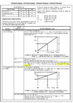
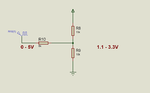
I have a communication circuit in which one section needs input at 1V for Logic 0 and 3.3V for Logic High. But the microcontroller outputs only 0V(low) and 5V(High).
Is there any simple solution to shift 0V to 1V and 5V to 3.3V ?
I found one level shifter with LP211, but looking for more simple solution.

Thanks
 

Usually a logic interface has other requirements like speed, rise time, tolerance on each level and then you may have other requirements like budget, real estate
 

This is an FSK Encoder(4046), which receives 1V(as Low) and 3.3V(as High) as its input, rather than TTL 0V and 5V.
The speed of communication is 2400 bps.
 

Hi,

there are many 4046 devices with different voltag levels, please give a more detailed partname.

Read it´s datasheet carefully.
I´m very sure it is not a fixed "1V" but the for example "max input for LOW " = 1V. So if you input 0V, then its OK.
The same is with High level.

********
BTW: TTL levels are not specified to be 0V and 5V. This is the usual supply voltage.
TTL input levels for a valid LOW are <=0.8V; and for HIGH >=2V
TTL input levels usually are not supply voltage dependent, but CMOS input levels are supply voltage dependent.

********

If you want to build a "universal level shifter" then use a digitally controlled analog switch (SPDT), and two OPAMPs generating the low level and the high level.
Feed the low_level_voltage to the NC pin of the SPDT and the high_levle_voltage to the NO pin of the SPDT.
The COM of the SPDT is your new level_shifted_output.

Klaus
 

Hi,

there are many 4046 devices with different voltag levels, please give a more detailed partname.

Read it´s datasheet carefully.
I´m very sure it is not a fixed "1V" but the for example "max input for LOW " = 1V. So if you input 0V, then its OK.
Klaus

I am using CD74HC4046A.
Please see the attached Datasheet Images, which says VCOin ranges.
 

Attachments

  • 4046_1.jpg
    4046_1.jpg
    279.2 KB · Views: 68
  • 4046_2.jpg
    4046_2.jpg
    184.4 KB · Views: 51

Hi,

VCO-in is an anlog input to set VCO frequency.

No digital input.

You need a regulation loop. either passive, or with OPAMP, or with DAC....

Klaus
 

Thanks Klaus.
But strange to the term regulation loop.

I am planning to add a resistor network such as the attached which I hope will do the needful.

Please comment.
Thanks
 

Attachments

  • Level_Shifter.png
    Level_Shifter.png
    9.5 KB · Views: 66

Hi,

I doubt it would work.

it seems you don´t recognize the function of the pin.
It is _not_ to switch something ON or OFF, not to switch HIGH or LOW.

It is to adjust frequency. You may connect a potentiometer to it.

******
Your circuit surely makes it possible to select two (or three) voltage levels. But the output frequency is not defined because the relatively huge V-f error.
Usually one needs a very precise freuqency when working with a VCO.

******
One possibility is to connect a capacitor in parallel to R9, then you are able to output a PWM from controller and get a variable output voltage and this giving variable frequency.
adjust: duty cycle ---> voltage --> frequency.

Klaus
 

Hi Klaus,

For the FSK modulator I need two frequencies for low and high states (only two states).
74HC4046 output frequency depends on the VCOin voltage. For me I have already tested it and it generates 30KHz for 0V and 33KHz for 3.3V. And I can even communicate successfully by using XR2211 Demodulator with a buad-rate of 2400 bps.
But I noticed some drift in frequency when temperature increases. So I started to study data sheet of 74HC4046 again and there is found a design recommendation of minimum 1.1V at VCOin pin, which I was doing with 0V. So I decided to follow the data sheet recommendation, by shifting 0V (low state) to 1.1V.

There is no need of PWM, duty cycle, etc.

Thanks
 

Hi,

Now i understand what you want to do.
Sorry if i confused you.

Frequency deviation from device to device is no problem?
And you don't need known and stable frequencies for transmitting HIGH and LOW?

So then your circuit is fine.

Klaus
 

Hi,

Frequency deviation from device to device is no problem?
And you don't need known and stable frequencies for transmitting HIGH and LOW?

Klaus

My communication involves several nodes which communicates with FSK.
Suppose all nodes are set to 30/33kHz. If one node's set frequency drifts (around 1.5KHz change by ambient temperature, it happens in my case with TSSOP package..! With DIP package it is fine), then detection(with XR2211) is not possible.
This is not the subject we are discussing though.

Anyway I tried the resistor network method to level shift 0 to 1.1V and 5V to 3.3V. It works fine.
But the temperature drift is still there. If you hold a hot Iron near to 4046 (TSSOP package), you can see frequency changing rapidly.

Thanks.
 

Status
Not open for further replies.

Similar threads

Part and Inventory Search

Welcome to EDABoard.com

Sponsor

Back
Top