Continue to Site

Welcome to EDAboard.com

Welcome to our site! EDAboard.com is an international Electronics Discussion Forum focused on EDA software, circuits, schematics, books, theory, papers, asic, pld, 8051, DSP, Network, RF, Analog Design, PCB, Service Manuals... and a whole lot more! To participate you need to register. Registration is free. Click here to register now.

[SOLVED] LED strip light with burnt LED, and how it functions, question(s)

Status
Not open for further replies.

d123

Advanced Member level 5
Joined
Jun 7, 2015
Messages
2,505
Helped
494
Reputation
992
Reaction score
525
Trophy points
1,393
Location
Spain
Activity points
27,148
Hi,

Was asked to look at this LED strip light, a low power replacement for flourescents, I know it was ...inexpensive..., not top of the range. This is the second out of three of these that have broken in a neighbour's home.

I looked, and it has a burnt LED (a black spot in the middle of the LED, and brown mark around edges). I also took it apart out of curiosity as it's odd that two should break in a few weeks of use.

Not sure if we have voltage surges here so high as to go breaking lights but not affecting other neighbours, their house seems to function "normally" electrically speaking, ... As I'm not well-versed in repair diagnosis, I am guessing that the LEDs may not be ideally matched, or a slight surge would tip the balance and something will blow, like an LED.

I've attached a schematic of the circuit, hope it's comprehensible and haven't made any mistakes copying the track paths; also a blurry photo of the burnt LED (maybe I'm wrong about it being burnt) and a photo of the ultra high-tech AC mains to DC circuit inside the strip light.

I wonder if the LEDs are bi-directional white LEDs, I'm having difficulty otherwise seeing how this circuit works. I used the symbol for a single LED as I have no idea how these little white and yellow rectangle LEDs are on the inside.

a) What may (appreciating it is guessing) be the cause(s) for two out of three fails in few weeks of use?

b) I don't know how to phrase this question, but, let's try with: Is the diode rectifier alone a normal way of powering this type of lighting?
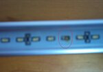
Burnt LED.JPGLed strip rectifier.JPGLED light strip schematic.JPG

Thanks
 

a. complete lack of voltage regulation and LEDs probably run at their absolute limits.
b. it works (obviously) and it gives DC out so they won't be bi-directional diodes but it isn't a method a good designer would use.

The LEDs are probably run beyond maximum current ratings and rely on the pulsed nature of the rectified AC to prevent them burning out immediately. The trouble with LEDS, like most diodes, is they are constant voltage devices. They like to be current driven so they can maintain their own voltage drop (Vf) according to the individual chemstry of the LED junction. In that strip light there is no current limit, it relies on the total voltage drop of all the diodes in series being very close to the DC applied across them and the internal resistance of the diodes to limit the current. That resistance produces internal heat. The applied voltage isn't constant, coming from a bridge rectifier it varies between 0V and a peak of about 311V every half mains cycle! Also consider that the current increases dramatically as the voltage increases slightly and the 220V AC is probably a nominal voltage and not guaranteed. For example, here the 'official' voltage is 230 AC at 50Hz but measuring it on an accurate true RMS DVM shows it is actually about 254V because I'm close to the distribution transformer (I actually have my own 3-phase cable direct to the transformer!).

It's difficult to modify to make it reliable without breaking the LED chain into two so each half needs less voltage, doing that would allow a regulator to be added. At the moment, the total Vf is so close to the input voltage that it wouldn't be feasible to add one. The best you can probably do is add a small series resistor (~10 Ohms) to further drop the current a little and add a TVS/Varistor across the LEDs to try to clip nasty spikes in the voltage.

Brian.
 
  • Like
Reactions: d123

    d123

    Points: 2
    Helpful Answer Positive Rating
Cheap junk made "over there" is not reliable. Maybe it used very cheap LEDs that had no datasheet or the designer cannot read.
LED strips that I have seen operate from 12VDC and can be cut between each group of LEDs.
 
  • Like
Reactions: d123

    d123

    Points: 2
    Helpful Answer Positive Rating
Hi,

Thanks for the detailed answer, Brian, much appreciated. Just wanted to be sure that it is really as poor quality and the missing link between lighting from tallow in a cave and the oil lamp as it looks, and the explanation is very helpful to learn.

I'm not touching that thing with a bargepole, main reason is it's impossible/a long task to find a ideal replacement LED, the neighbour was just curious as to why two burnt out. Like the idea about the additional resistor and a TVS/varistor, thanks very much.
 

This LED strip is suited only to rated line voltage for the design which may be exceeded in your location.

The design uses the ESR of each LED set plus the series resistor.
LEDs cannot handle a wide range of current above the average DC rated current. Typically the ratio is only 2~3 for Peak/DC max

The 4 diode bridge simply rectifies the 230Vac rms to 141%= 325Vdc peak and an average DC voltage of 63% of Vpk or 90%of rms or 207Vdc avg

How many LEDs are in the strip?
The peak and average current can be calculated from this.


My educated guess is they used mismatched LEDs in the 2P arrangement and one failed from thermal runaway ( the one with initially lower ESR)

White medium power LEDs can be approximated like a zener by Vf=2.7V + If*ESR and let ESR = {2.5Ω & 5Ω} respectively in 2 LEDs in parallel, Vf= 2.7+0.15*{2.5,5} = {3.075V, 3.4V} Thus the lowest ESR LED draws most of the current, it gets hot and Vf drops with rising temp (runaway) so at a minimum it already is consuming the current of 2 LEDs and is probably exceeding the rated max current and burns up instead of drawing 1/8 or 1/4 W is now 200% of design power dissipation.

Conclusion.
My hunch is bad process control on LED sourcing and mixed bag assembly triggered by overvoltage on your mains.

Recommendation
After you tell me how LEDs in a string and max Vac you expect, I would suggest a suitable halogen lamp ( e.g. 300W ) in series to regulate the current. This will adjust the filament resistance to maintain a constant current and provides a small voltage drop.

With this you can safely short out the burnt LED group and use the others as spares.
 
  • Like
Reactions: d123

    d123

    Points: 2
    Helpful Answer Positive Rating
The first post shows a total of 35 groups in series where each LED has another LED parallel with it and each group is 5.1 ohm resistor in series with two series LEDs.
 

If you get a lot of transient voltages from power interruptions, then you need a line filter or at least a choke and a cap ( plastic 0.1uF@450V) across the DC.

If it is from sustained over-voltage like 10%, the resistors may get hot too.

I estimate as follows
230V *(1+10%) * √2= 350Vp,
thus 350V/35 groups = 10Vp per group

With 2S2P LEDs. With Rs=5.1Ω and LED ESR=2.5Ω above 2.7V*2 gives Vf=5.4V+ (5.1+{2.5~5Ω}*If =10Vp

thus If pk= (10Vp-5.4V) / {7.6~10.1}Ω = {602~455mA} Since the LED's only conduct when Vf > 3*5.4 = 189V out of a peak Voltage of 359Vp, I can estimate the power duty cycle is ~50%. (+/-10)

Since 35 strings will have 35*(Rs+ESR)= total ESR = {266~354Ω} range
For reliability I would add a aline filter and a 50~100 Ω PTC

This can be a suitable AC light bulb with this range of cold resistance in series. It should light up very dim.

I would also add a 0.1uF across the Bridge DC rated at 500V with a 1A 100uH choke on AC side. This would attenuate 3kV 10us spikes down to 500V. A larger choke is better.

By all means you can repair these strings with care.
 
  • Like
Reactions: d123

    d123

    Points: 2
    Helpful Answer Positive Rating
Hi,

Thanks for the explanation of probable cause and what happens when the LED burns, nice to understand why.

After thinking about it, and Brian's suggestion, and now Sunny's, and looking at prices of TVSs (wanted to make sure a bit of PM costs less than actual lamp), I was thinking perhaps worth modifying the working one they have, and with the two that are broken, trying to get an LED off one so as to replace the burnt one on the other - despite reservations about matching, but that could be most optimistic attempt at matching/repairing one of two, given my skills.

There is limited space (1.5cm x 1cm x 1.5metres) inside the lamp frame, and the lamp is 16W, point of replacing flourescents that use 60W is to keep power consumption low.

I'd wondered about this - I thought most things have a Y capacitor. As mentioned, a plastic 0.1uF@450V would be good.


If some-one could confirm this, to avoid errors: to do the lowest cost repair:

Y cap across AC L and N (plastic 0.1uF@450V)?

10R (? Watts) on DC V+ or V- end of whole string.

TVS rated for clamping at ~330 VDC? Is uni-directional correct choice? Placed across DC V+ to V-.

(Combined with TVS) Varistor/MOV to clamp at same voltage: ~330 VDC? Placed across DC V+ to V-.

Thanks for any input.

- - - Updated - - -

...Also, nearly forgot: If I remove an LED from one of the faulty lights, how could I jumper the space where there are two missing? Would a resistor be okay.

Sorry for so many questions, but I only make silly little DC circuits, which I find hard enough to get right, and as this is for some-one else don't want to have a carefree "There you go, a bad/dodgy repair, but I vaingloriously think it's great." attitude.
 

Whether you can replace the part or not probably depends on the substrate it is mounted on. The LEDs and resistors probably run very hot so the backing material (PCB) may be aluminum. If it is, you will have trouble soldering to it, the heat will be dissipated and you will not get the solder to melt. In manufacture, the whole strip would be soldered in one high temperature cycle, either under intense IR heaters or under boiling fluid.

You need to replace it with something to maintain continuity, I'm guessing at the moment the whole strip is dead because of that single break in the circuit. What I would do is this: connect a test meter across one of the resistors and prepare to measure the voltage across it. Then momentarily short out the damaged LED, it will make the others light up and you can measure the voltage dropped across the resistor. Keep it brief as the remaining LEDs will be even more overloaded. Also be extremely careful, you are working with un-isolated mains voltages. From the voltage drop you can estimate the normal working current (I = V/R) where V is what you measured and R is the resistor value. The value is rectified AC so it will not be quite the same as DC but as an estimate it will be adequate. Now repeat the test but this time measure the voltage across one of the working LEDS, this will tell you how much you need to drop in order to mimic the bad one. Then use Ohms law to work out the equivalent resistance and power rating you need. R = Vf/I where Vf is the LED voltage and I is the current you calculated. The power the resistor will dissipate is Vf* I.

You need to do more than just fit voltage clamps across the voltage as you will be trying to protect the whole neighborhood! Wire a choke in series with the incoming AC first as Tony suggests then a capacitor across the input side of the bridge. Use an X2 rated capacitor, it doesn't matter which AC wire you connect the choke. It will reduce the chances of further damage but it isn't the ideal solution.

Brian.


You can short out the 2S2P cluster which only drops the threshold voltage of the LED 2.7V zener voltage from Vth 35*5.4 = 189V to 34*5.4= 183.6V out of a worst case 230V +10% peak voltage of 350V.
So it is siginificant but no need to do anything except add an AWG 30 jumper and remove the good LEDs with a 125W gun if on Alum-clad board. When you add 50 cent tungsten bulb in series instead of running 100W it acts as a constant current limiter.

Let me regurgitate.

e.g. 230V@100W , Rh=529 Ω . We know cold tungsten is 10% of hot rated Rh, so Rc= 53 Ohms
Since I know each 2S2P LED string is 2.5~5Ω the total ESR plus fixed R=5.1 then,

Rtotal= 7.6 to 10.1 Ω * N strings. Now reducing N from 35 to 34 only reduces Rtotal by 3% !! which is not much. If Rtotal= 7.6Ω*34 =258Ω adding the 100W 230Vac bulb in series now makes it 258+53Ω which reduces the peak current by 53/311= 10.3% which not only adds considerable margin for overvoltage and easily makes up for 1 string of 7 to 10 Ω's.

However in terms of practical nature, this design is not very efficient with all the 5.1 Resistors.
A high efficiency tri-phosphor T8 x4ft tube will be 88 Lumens /watt and last 30k to 50k hours. with better phosphor than a white LED and you can run 1 to 4 tubes from one ballast with 25 to 30W per tube depending on cost/choice.

Get a proper commercial LED tube !!! Your DIY choice is worse. THis is not intended to be an efficient use of LED's just a voltage tolerant ( but not tolerant enough for your location if indeed it is designed for 230V !! let alone 250V.

This strip is for special applications where a tube may not be suitable..

It will be more efficent than a tungsten bulb but less than a good FL tube.
Unless the LED bulb or tube is > 88 LPW, a fluorescent tube is better and cheaper.
 

Tony, I think d123 is in Spain. In the European Union there are rules and regulations about the types of lighting that can be used these days. Some tungsten lamps are now unavailable and not permitted in new installations. I don't know the specific circumstances in d123's case but here I built a new house and to comply with building regulations I had to install all LED or CFL lighting.

It's good from an eco point of view but the downside is a certain country "'over there" as Audioguru calls it, dumps low quaility lights to satisfy the market demand.

Brian.
 

YOu can get LED tubes from 75 to 120 Lumens per Watt (LPW) for $30
or get FL tubes from 75 to 88 Lumens per Watt for $8 with tri-phosphor true daylight, long life 30kh min to 50kh max if left on all day.
CRI quality can be better on FL tubes with triphosphor but worse with cheap 2 phosphor FL tubes for $2 are N.G.

I prefer FL shown here **broken link removed**
 

Hmmm, Brian must have seen my IP!

Absorbing the information and advice provided, for what was a low cost purchase, something we all do, there seems little to be gained from a Frankenstein job on the LED strip lights, and more sense in replacing them with better quality devices. If civilised society collapses, then it'll be worth repairing them, but not before... :)

Along with the impressive mathematical explanations, much appreciated, really, and the useful trouble-shooting and repair advice, again, I've learnt a lot from this thread, I conclude what I think deep down is correct - still surprised such things slip through the net, wherever they are made: designed to fail and/or you get what you pay for - and one reason why the less affluent remain less affluent: partly by having to buy cheap, worthless tat 100 times over because they can never afford a quality version the first time, ironic but not good to dwell on. It amazes me how things can be manufactured and sold which really leave much to be desired and no-one bats an eyelid - yet a mass produced IC that costs a few cents/pennies is good quality and can last 50 years? I have a cheapo phone that is pretty bad, poor soldering, bad connections, move your head slightly mid call and the person at the other end no longer hears you or vice versa... it's all resistors, diodes and capacitors, except for the LCD display...

Really, many thanks, I'll see what the neighbour wants to do, but as said, see little good coming of a repair job.

Daniel
 

Status
Not open for further replies.

Similar threads

Part and Inventory Search

Welcome to EDABoard.com

Sponsor

Back
Top