Continue to Site

Welcome to EDAboard.com

Welcome to our site! EDAboard.com is an international Electronics Discussion Forum focused on EDA software, circuits, schematics, books, theory, papers, asic, pld, 8051, DSP, Network, RF, Analog Design, PCB, Service Manuals... and a whole lot more! To participate you need to register. Registration is free. Click here to register now.

LED driver LM317 schematic

Status
Not open for further replies.
20150710_141857.jpg

Not very complicated! The two inputs are either connected to ground or +5V. If you use a LED you should also add a resistor to limit the current to the LEDs maximum rating. If you need more than 5V for the LEDs, stabilize the voltage to the PIC at 5V (a Zener will do, it only draws about 1mA) and increase the voltage at the top of the load. There will be a limit to how high you can go if you use a MOSFET unless you use a logic level type or add an additional driver transistor to lift the gate voltage to nearer the drain voltage.

I suppose a single pot could serve as a btrightness set when the lamp operates. In that case, where shall one put this pot, at the transistor base or at the emitter? (pot power constraint)
The plan is the transistor fully saturates (= max brightness) when the capacitor has fully charged. If you add additional resistance to limit the base current you put it back in the mode where it dissipates most heat and also increase either the capacitor charge time (with R1) or discharge time (with R2).

I also would like the led ground to be connected at the ground point (body of the lamp, so I will probably try connecting the collector directly to vcc and put the resistor/led on the emitter side, I hope this will be ok.
It will still work but not properly. The reason is the transistor is brought into conduction by injecting current into it's base. To do that, the base voltage has to be higher than the emitter voltage. With the load in the emitter, the emitter voltage will rise with the current and tend to cut off the voltage creating the bias current. It limits the top current you can achieve and also stops the transistor conducting at all until the base voltage is Vbe + Vf of the LED. You will get slightly better results with the resistor in the collector and LED in the emitter because that keeps the emitter voltage constant as long as you have enough base voltage to make it conduct.

Brian.
 
You will get slightly better results with the resistor in the collector and LED in the emitter because that keeps the emitter voltage constant as long as you have enough base voltage to make it conduct.
Brian.

Ok I will try that in the weekend.
Do you think, will this be able to drive the paralleled leds if using a more powerful transistor? I do not see why not, but I was confused by audioguru's post above.
 

What Audioguru was saying is that if you want to keep the LED in the ground side, it would be better to drive it from the collector of a PNP transistor, in other words, 'turn it upside down'. The drawback to that is the base voltage now has to be brought lower than the supply to turn the LED on instead of higher than ground.

You can use a transistor with higher current capability to drive more LEDs in parallel but remember the base current also increases (Ib=Ic/Hfe) and that you should not connect LEDs directly across each other. Being constant voltage devices, the one (or chain if you have several in series) with lowest Vf will hog most of the current. You should add resistors in each LED or chain to help balance the current.

If you try with the LED in the emitter, bear in mind the base voltage has to be ~0.6V higher than the emitter voltage and the emitter will be held at Vf of the LED. You might need several volts on the base before the transistor conducts.

Brian.
 
  • Like
Reactions: neazoi

    neazoi

    Points: 2
    Helpful Answer Positive Rating
My very cheap Chinese flashlight has 24 white LEDs connected directly in parallel. There is no current-limiting resistor since the cheap carbon-zinc AAA battery cells limit their current. All the LEDs have the same brightness.
Of course they pay somebody a bowl of rice a day to test, chart and sort millions of LEDs into groups that have exactly the same forward voltage.

I have tested this today https://i.stack.imgur.com/XAC7B.png
My version has these changes:
R1 is ommited.
Q1 is a bd433
c1 is 3000uF at 6v3
bat is 12v
r1 is 6k8
r2 is 100R

This configuration with these components, achieves a smooth start up (about 5sec) and a smooth shutdown (15-20sec) with most of the light to go out within 10 sec from switch off.

I am very satisfied. However:
The total consumption of the lamp and the regulator is 400mA at 12V. Not too god but acceptable regarding the simplicity of the circuit.

The only really bad thing is that when the lamp is switched off (sw1 open), Vbatt still exists on the circuit, eventhough the lamp brightness is switched off.
I would like to add a delay switch in series with the Vbatt probably, so that after the lamp has been switched off (after say 20 sec or so), this switch will disconnect the batt from the circuit.
Now I am just switching off the Vbatt with a second switch manually.

Any ideas of how this could be done?
 

I see you have ignored all my advice, so far, so I will keep this short.

  1. The 3mF cap.. Remove it. If you want a slow turn on there are better ways.... Use a MOSFET.
  2. The LEDs were not defined. What are they?
  3. What can possible draw 450mA in this design unless R3 is <20 Ohms.
  4. The LED series string should add up to more than 9V then use Ohm s law on the difference to set current.
  5. Vce sat to be low must be biased with 10% of LED current with only one Rb from 12V.
  6. For zero drive current use and N Channel MOSFET and adjust R pullup * C for 1 second. e.g. 0.1uF * 10M
 
  • Like
Reactions: neazoi

    neazoi

    Points: 2
    Helpful Answer Positive Rating
I see you have ignored all my advice, so far, so I will keep this short.

  1. The 3mF cap.. Remove it. If you want a slow turn on there are better ways.... Use a MOSFET.
  2. The LEDs were not defined. What are they?
  3. What can possible draw 450mA in this design unless R3 is <20 Ohms.
  4. The LED series string should add up to more than 9V then use Ohm s law on the difference to set current.
  5. Vce sat to be low must be biased with 10% of LED current with only one Rb from 12V.
  6. For zero drive current use and N Channel MOSFET and adjust R pullup * C for 1 second. e.g. 0.1uF * 10M

Hey do not take it personally :)
I avoid the use of fets where I can. I do not know but most of my constructions using fets end up in the recycle bin. Maybe it is my misunderstanding of their characteristics, I can tweak npn bjts much better.
But the main issue was components availability. I just used what I had in the lab. Now that my country is gradually preparing for an EU exit, it is very difficult for me to raise paypal funds to buy new stuff. That's a shame...
 

You can achieve good current limiting and higher efficiency by simply matching the supply voltage to the Vf of a string of LEDs at desired current below max. Then use a series R with Ohms Law for small mismatch <2V at defined current operating point. This should be in the range of 0.1Ohm per Amp to 2 Ohms per Amp. Your source if it is a battery ESR must be included.

your schematic only showed 1 LED with a huge 9V? drop in voltage,which is very inefficient. So I suspect it is shown incorrectly.

If it is a SMT reel or stripled they will already be current limited with series R and many parallel arrays and you must concern yourself with long wire inductance and harmful reverse voltage spikes to LEDs. So depending on V=LdI/dt you will need a diode clamp to Vbat or a smoothing cap on the output for a low side switch.

The voltage drop in the switch and current drive requires that for any BJT the base current must be 5~10% of the Collector current which makes C rather large or BJTs and very small for MOSFETs. FETs need to have low on resistance to prevent heat loss <0.1 Ohm in thus case.

cant you specify or show what LEDs are used?
 

Here is the program I tried. Please note it was written and tried in about 10 minutes from start to finish and only done as proof of concept. I'm sure it can be made more efficient and reliable with a little effort. I didn't do any debugging at all.

It was written in FED's Wiz-C Pro compiler using the rapid development tool so if you use a different one you will need to add some library code.
Code:
#include "C:\\projects\\PWMDimmer\\PWMDimmer_Auto.h"

unsigned int Target = 0;
unsigned int Present = 0;
unsigned int ADCValue = 0;

//*******************************************************************************
//
void UserInterrupt()
{
 #asmline SETPCLATH UserIntReturn,-1  ; SETPCLATH for interrupt routine
 #asmline goto UserIntReturn	      ; Assembler - go back to interrupt routine
}


//*******************************************************************************
//
void UserInitialise()
{
	OSCCON = 0x71;
	OPTION_REG |= 0x80;
	TMR1H = 0xB1;
	TMR1L = 0xE0;
	ADCON0 |= (1 << GO_DONE);
}

//*******************************************************************************
//
void UserLoop()
{
	if(OnOff == 0) Target = 0;
	else Target = ADCValue;
}

//*******************************************************************************
//
void ADCFinished()
{
	T1CON &= ~(1 << TMR1ON);
	ADCValue = (unsigned int)ADRESH << 8;
	ADCValue += (unsigned int) ADRESL;
	T1CON |= (1 << TMR1ON);
	ADCON0 |= (1 << GO_DONE);
}

//*******************************************************************************
//
void TenMsTick()
{
	T1CON &= ~(1 << TMR1ON);
	TMR1H = 0xB1;
	TMR1L = 0xE0;
	T1CON |= (1 << TMR1ON);

	if(FastSlow == 1)	Present = Target; // fast mode	
	
	else
	{
		if(Present < Target) Present++;
		else if(Present > Target) Present--;
	}
	
	SetPWM1Volts(Present);
}

Brian.
 

Attachments

  • PWMDimmer.zip
    979 bytes · Views: 46
  • Like
Reactions: neazoi

    neazoi

    Points: 2
    Helpful Answer Positive Rating
Here is the program I tried. Please note it was written and tried in about 10 minutes from start to finish and only done as proof of concept. I'm sure it can be made more efficient and reliable with a little effort. I didn't do any debugging at all.

Brian.

Thanks Brian! I will try it when I get the micro.
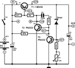
In the meantime I have tried this regulator. It is a slightly modified version of the "thrifty voltage regulator" and it was modified for higher current based on a previous threat in this forum.
The regulator works very well and avoids the higher input voltage required by other linear regulators, yet using discrete components. Voltages are shown for 9v in and 4.5v out but It can work fine on 3v output as well by just replacing the zener.
The only thing I have noticed is that despite the fact that the output voltage remains stable, the current at say 3.5v input is a bit low, at about 200mA, whereas the leds require 400mA. When I increase the input voltage to say 12v The output voltage is increased only 0.1-0.2v and the currend drawn by the leds is 400mA.

Shall I decrease further the values of R2 and R4 to correct this problem? (assumming that it is a T1 base current starving problem)

Also, have you got any ideas of how a simple decay could be added to the circuit, if this can be done on that one (assumming a vin of say 12v)? I could add a second series stage of decay, like I did before, or using your PWM circuit in conjunction with this regulator maybe.
Any ideas would be interesting.
 

Attachments

  • thrifty_voltage_regulator_circuit_diagram.gif
    thrifty_voltage_regulator_circuit_diagram.gif
    24.2 KB · Views: 73

Sorry for the late reply.

The schematic is a voltage regulator, you really need a current regulator. As you noted, a very small change in voltage causes a large change in current, this is because the voltage has reached the Vf of the LEDs and from there on they will clamp the voltage by drawing as much current as they can. If you could increase the voltage by maybe another 0.1V you would likely destroy the LEDs due to overcurrent. If you control the current instead, the LED voltage will remain almost constant but the brightness will vary, I think that's what you really want.

Please remind me what the LED Vf and current ratings are and how much voltage you have available at the power source.

Brian.
 
  • Like
Reactions: neazoi

    neazoi

    Points: 2
    Helpful Answer Positive Rating
Status
Not open for further replies.

Similar threads

Part and Inventory Search

Welcome to EDABoard.com

Sponsor

Back
Top