vespucci
Newbie
Hello.
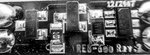
I would need some help identifying the little controller circuit board which was connected before a LED.
It is a Transom Light of a boat with a 5mm blue LED. It was connected to 12V(13.4V) and hit by a lightning surge. The LED itself was tested and is still ok but at the output of the board we have 0V.
Can somebody identify the board or the parts?
Thanks,
VESPUCCI
--- Updated ---
Hello.
I would need some help identifying the little controller circuit board which was connected before a LED.
It is a Transom Light of a boat with a 5mm blue LED. It was connected to 12V(13.4V) and hit by a lightning surge. The LED itself was tested and is still ok but at the output of the board we have 0V.
Can somebody identify the board or the parts?
Thanks,
VESPUCCI