Continue to Site

Welcome to EDAboard.com

Welcome to our site! EDAboard.com is an international Electronics Discussion Forum focused on EDA software, circuits, schematics, books, theory, papers, asic, pld, 8051, DSP, Network, RF, Analog Design, PCB, Service Manuals... and a whole lot more! To participate you need to register. Registration is free. Click here to register now.

learning to use MultiSim

Status
Not open for further replies.

PG1995

Full Member level 5
Joined
Apr 18, 2011
Messages
248
Helped
1
Reputation
2
Reaction score
1
Trophy points
1,298
Activity points
3,758
Hi

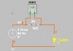
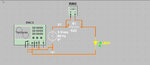
I'm learning to use MultiSim. I have never used any such software before. This following link has the video of the circuit I made:
YouTube - ‪multisim1.avi‬‏

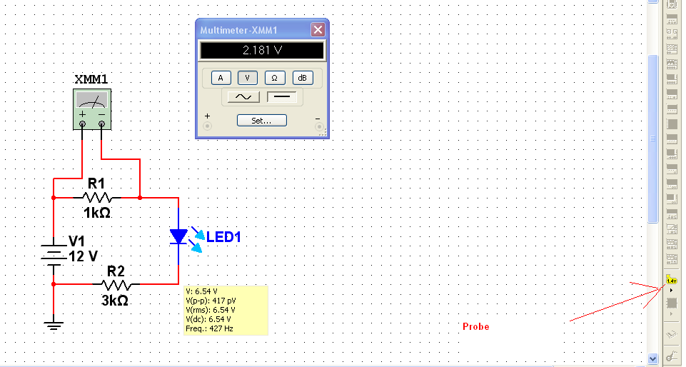
I don't know how to find voltages across R1 and R2. When I press simulation button nothing happens except those green bars. Could you recommend me some book to learn MultiSim? Do you have any other suggestion? Please let me know.

Regards
PG
 

Simply press simulation button and click on voltmeter or use measurement probe
 
Thanks a lot, Jony. I think I have learned the use of the probe. Pleas have a look on the linked screenshot:
https://img64.imageshack.us/img64/9702/multisim2.jpg

What would be the best way to learn to use MultiSim in your opinion? Should I get some book?

By the way, you see the probe also shows a frequency value, what is it? It's a DC circuit.

Best wishes
PG
 

Thanks a lot, Jony. I think I have learned the use of the probe. Pleas have a look on the linked screenshot:
https://img64.imageshack.us/img64/9702/multisim2.jpg

What would be the best way to learn to use MultiSim in your opinion? Should I get some book?
Use the Internet to learn the bases, and pres F1 to help. Multisim is a simple program to use you don't need a book.

By the way, you see the probe also shows a frequency value, what is it? It's a DC circuit.
I don't have a clue. Maybe it's just another error in the program.
And I think that the best spice software is LTspice or Micro-Cap.
Somehow I don't like multisim very much.
 

Once again, thanks. But as far as I know (and mind you I know very little!) MultiSim is very popular. I have seen some books recommending it and using it.
 

you just double click on meter.. you don't need to any changes to you circuit.
just double click on meter , when you run circuit . and pop up will show u result.


Simply remove all unnecessary "tools" :cool:
Keep it clean :grin:

Thanks, Jony. But I like it unclean! :wink:

Actually having many toolbars at hand makes learning easy, at least this is true for me. So, is this possible to fix the misalignment of the toolbars? Any guess?

I think when I turn the simulation on, the circuit is activated. Then, why doesn't the diode emit blue light when simulation is turned on (please have a look on the video in my first post above). If I had the circuit in real life then the LED would definitely emit the blue light.

Best wishes
PG
 

In the multisim the LED will emit blue light when the LED current is greater then 5mA.
But of course you can change the LED ON current, just double click on the LED and change to ON current.
OR you could change the resistor to gets 5mA.
 

Thank you.

Please have a look on the following video: REMOVED

The color of LED doesn't change whether the simulation is on or off.
 

Attachments

  • scnshot.jpg
    scnshot.jpg
    286.8 KB · Views: 81
Last edited:

It some stupid error. Simply change the ON current to 5mA switch on/off the simulation. And change the current again.
At least it's works for me
 

The circuit is grounded but I don't know why it doesn't work. I have linked the MS circuit drawing:
**broken link removed**
 

Attachments

  • msimprob.jpg
    msimprob.jpg
    225.1 KB · Views: 81

Know the circuit is working, all I have done to the circuit is to delete all the wires "place" the new one.
This is why I don't use the multisim
 

Attachments

  • Circuit1.rar
    41.7 KB · Views: 70

Your gnd is not connected, move it a little lower , delete the connection and rewire the gnd

Alex
 

Thanks aa lot, Jony, Alex.

I was experimenting an AC source of 120V; the resistor is blown up. How do I fix it again to make it work without inserting a new one from the list?

Thanks for all the help.
 

Attachments

  • acsrcems.jpg
    acsrcems.jpg
    45.4 KB · Views: 98


Thanks, Alex. It did work.

Now I was experimenting with an o-scope. I was expecting to see a clipped sine wave above x-axis. But it doesn't show. I hope I have the connections right. I have connected both terminals of the circuit to CH 1. What's the reason?

You can have a look on this video: YouTube - ‪msoscopevid.avi‬‏
 

Attachments

  • msoscope.jpg
    msoscope.jpg
    93.2 KB · Views: 84

I would be surprised if the oscilloscope showed anything different, you have connected the input to gnd...

Alex
 
  • Like
Reactions: fareen

    fareen

    Points: 2
    Helpful Answer Positive Rating
Status
Not open for further replies.

Part and Inventory Search

Welcome to EDABoard.com

Sponsor

Back
Top