T
treez
Guest
Hello,
We are designing an offline (230VAC) 3kW, half bridge LLC converter (battery charger) The LLC stage has an input voltage of 340VDC to 435VDC. [f(resonant) = 100kHz]
Its output voltage is 300-400VDC.
We must use an PQ3535 ferroxcube (3C90) transformer. (we are using a gap so it has AL = 1600). We cannot use any bigger transformer due to space constraints.
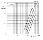
The ferrite core delta B will be 450mT.
The worst case secondary current is 10A RMS. Worst case Primary RMS = 17.8Arms
In order to get the winding loss down we will have to wind the transformer as follows…
Primary = 20 turns
Secondary = 36 turns.
We need low-as-possible leakage inductance so we will sandwich the 20 primary turns between the secondary halves
So we have…
18 secondary turns (2 layers)
20 primary turns (2 layers)
18 secondary turns (2 layers)
The primary turns are litz-wound, 7 strands of 0.4mm ECW
The secondary turns are litz-wond, 7 strands of 0.315mm ECW
This means we get 7W of winding loss in both primary and secondary, so that’s 14W of winding loss total.
We are hoping that such a stack-up of turns doesn’t give us too much proximity loss.
There are 3mm margin tapes each side of bobbin.
Do you think that we can achieve a coupling of 0.998 between primary and secondary like this? We need to have at least that coupling because if the leakage is too high, then the LLC’s resonant frequency will be too low.
We are designing an offline (230VAC) 3kW, half bridge LLC converter (battery charger) The LLC stage has an input voltage of 340VDC to 435VDC. [f(resonant) = 100kHz]
Its output voltage is 300-400VDC.
We must use an PQ3535 ferroxcube (3C90) transformer. (we are using a gap so it has AL = 1600). We cannot use any bigger transformer due to space constraints.
The ferrite core delta B will be 450mT.
The worst case secondary current is 10A RMS. Worst case Primary RMS = 17.8Arms
In order to get the winding loss down we will have to wind the transformer as follows…
Primary = 20 turns
Secondary = 36 turns.
We need low-as-possible leakage inductance so we will sandwich the 20 primary turns between the secondary halves
So we have…
18 secondary turns (2 layers)
20 primary turns (2 layers)
18 secondary turns (2 layers)
The primary turns are litz-wound, 7 strands of 0.4mm ECW
The secondary turns are litz-wond, 7 strands of 0.315mm ECW
This means we get 7W of winding loss in both primary and secondary, so that’s 14W of winding loss total.
We are hoping that such a stack-up of turns doesn’t give us too much proximity loss.
There are 3mm margin tapes each side of bobbin.
Do you think that we can achieve a coupling of 0.998 between primary and secondary like this? We need to have at least that coupling because if the leakage is too high, then the LLC’s resonant frequency will be too low.