jaguar10
Newbie level 4
- Joined
- Nov 11, 2011
- Messages
- 6
- Helped
- 0
- Reputation
- 0
- Reaction score
- 0
- Trophy points
- 1,281
- Location
- Lima (Perú)
- Activity points
- 1,341
Hello everyone, good day;
I am developing a proyect where a little part of it is to sense the intensity of the daylight. I am using of course using LDRs.
The regular circuit would be a voltage division between a resistance and the LDR, next would be an opamp buffer to separate impedances between circuits so that it can finally go into the ADC pins of the ATmega8.
The problem is that my physical space is pretty much limited. And since I am using 6 LDRs, i would need 6 buffers, and that is quite a lot of space in my circuit board.
So i was checking the ATmega8 datasheet and there no information about the internal impedance of the ADCs...
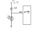
I know its not wise to make this connection:

but its the best i can do right now...
So my question is:
Does anyone know how much ohms does the ADC of the ATmega8 has?
And the rough connection i am proposing would work?
PD: Sorry about the circuit image, i did it on paint in 5 seconds... im not a child
I am developing a proyect where a little part of it is to sense the intensity of the daylight. I am using of course using LDRs.
The regular circuit would be a voltage division between a resistance and the LDR, next would be an opamp buffer to separate impedances between circuits so that it can finally go into the ADC pins of the ATmega8.
The problem is that my physical space is pretty much limited. And since I am using 6 LDRs, i would need 6 buffers, and that is quite a lot of space in my circuit board.
So i was checking the ATmega8 datasheet and there no information about the internal impedance of the ADCs...
I know its not wise to make this connection:

but its the best i can do right now...
So my question is:
Does anyone know how much ohms does the ADC of the ATmega8 has?
And the rough connection i am proposing would work?
PD: Sorry about the circuit image, i did it on paint in 5 seconds... im not a child