Continue to Site

Welcome to EDAboard.com

Welcome to our site! EDAboard.com is an international Electronics Discussion Forum focused on EDA software, circuits, schematics, books, theory, papers, asic, pld, 8051, DSP, Network, RF, Analog Design, PCB, Service Manuals... and a whole lot more! To participate you need to register. Registration is free. Click here to register now.

[SOLVED] LCD interfacing with PIC16F628A

Status
Not open for further replies.

speedEC

Full Member level 6
Joined
Apr 1, 2011
Messages
337
Helped
23
Reputation
46
Reaction score
21
Trophy points
1,298
Activity points
4,324
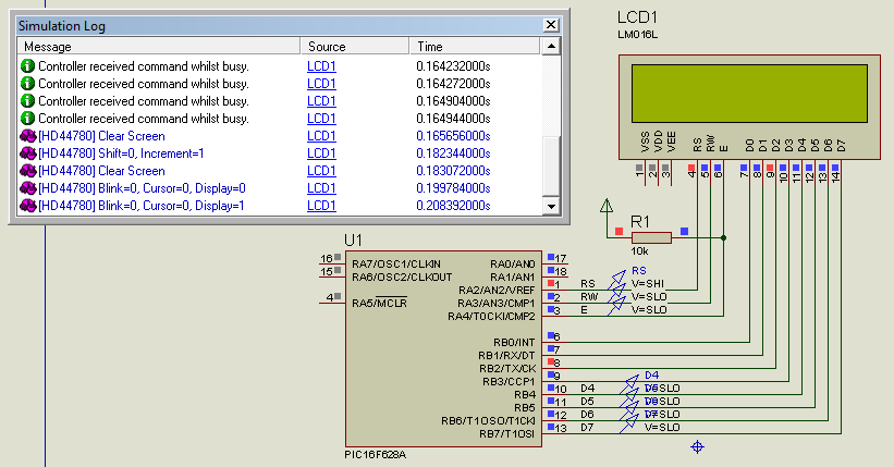
I like to Interface JHD LCD (2x16) with PIC16F628A. I connected the pic ports to LCD and I build the project. But LCD Blinks and not showing any characters on LCD. I have modified the lcd.c according to PIC16F628A like this:

Pin Connections:

(LCD to PIC MCU):


Code C - [expand]
1
2
3
4
5
6
7
8
9
10
11
12
13
14
15
16
17
18
19
20
21
22
23
24
25
26
27
28
29
30
31
32
33
34
35
36
37
38
39
40
41
42
43
44
45
46
1. GND to GND
2. Vcc to +5V
3. Vee to 10K pot to +5v (Contrast)
4. RS to RA2
5. R/W to RA3
6. E to RA4
7. D0 to GND
8. D1 to GND
9. D2 to GND
10. D3 to GND
11. D4 to RB4
12. D5 to RB5
13. D6 to RB6
14. D7 to RB7
15. LED+ to +5v
16. LED- to GND
 
lcd.c (modified):
 
.
.
.
#define LCD_RS RA2
#define LCD_RW RA3
#define LCD_EN RA4
 
#define LCD_DATA    PORTB
.
.
.
 
lcd_init()
{
   char init_value;
   
   //ADCON1 = 0x06; // Disable analog pins on PORTA
   
   TRISA=0;
   TRISB=0;
   
   CMCON = 0b00000111;  // disable comparators
   init_value = 0x3;
   .
   .
   .
}


main() file:


Code C - [expand]
1
2
3
4
5
6
7
8
9
10
11
12
13
14
15
16
17
void main(void){
    
    TRISB = 0x00;
    TRISA = 0x00;
    CMCON = 0b00000111; // disable comparators
    PORTB = 0x00;       // all low
    PORTA = 0x00;
    
    lcd_init();
    lcd_clear();
    lcd_goto(0);    // select first line
    lcd_puts("12345678");
    lcd_goto(0x40); // Select second line
    lcd_puts("Hello world");
    
    for(;;);
}


IDE & Compiler: MPLAB IDE v8.63
: Hi-Tech C

Any help?
Thanks
 
Last edited:

This is the hex file. Please update me the result.

Thanks
 

Attachments

  • LCD_Trial.txt
    1.1 KB · Views: 68

We forgot that pin A4 can drive only down transistor ))))

Even then pins D0-D3 must be connected to portb too. That's a not optimal code for this lcd. I'm using 4-bit control without ready flag - only 6 pins needed.

---------- Post added at 11:06 ---------- Previous post was at 10:58 ----------


---------- Post added at 11:18 ---------- Previous post was at 11:06 ----------

Sorry, even with 8bit wide don't work too. Please, use another pin and recompile you project again.
What frequency of CPU do you use in project?
 
Last edited:
I am using 4MHZ crystal frequency. I have to use 3 pins for ADC from Sensor. So, I need some pins free. Should I connect D0-D8 pins to MCU?

thanks

---------- Post added at 16:14 ---------- Previous post was at 15:55 ----------

Easyrider83, I have changed the pin RA4 to RA1 (for E). I got some garbage data on LCD (on one entire top line). But, no cursor blinks or no valid data. Any help?

thanks

---------- Post added at 18:02 ---------- Previous post was at 16:14 ----------

Hi Easyrider83. Now LCD is working good. I don't have much knowledge on debugging process. But, I tried to change the output format from hex to binary in "watch window" on PORTB so that I can easily understand. I found changes occurred only on LSB of PORTB (b0 to b3) and no change found on MSB (b4 to b7). So, I tried changing connections that I already made, that is, D4 to D7 to RB0 to RB3. Now entire thing works fine. Thanks a lot for your help.
 

Status
Not open for further replies.

Similar threads

Part and Inventory Search

Welcome to EDABoard.com

Sponsor

Back
Top