Continue to Site

Welcome to EDAboard.com

Welcome to our site! EDAboard.com is an international Electronics Discussion Forum focused on EDA software, circuits, schematics, books, theory, papers, asic, pld, 8051, DSP, Network, RF, Analog Design, PCB, Service Manuals... and a whole lot more! To participate you need to register. Registration is free. Click here to register now.

Lcd interface with 89c51

Status
Not open for further replies.

mrarslanahmed

Full Member level 2
Joined
Nov 15, 2011
Messages
143
Helped
6
Reputation
12
Reaction score
6
Trophy points
1,298
Location
gujranwala pakistan
Activity points
2,205
I AM TRYING A HALLO WORLD PROGRAM ON LCD BUT ITS NOT WORKING

I DOWNLOADED DIFFERENT TUTORIALS AND WORKED THE WAY GIVEN IN THOSE TUTORIALS...

MY CODE IS:

ORG 00H

MOV A,#38H
ACALL COMNWRT

MOV A,#38H
ACALL COMNWRT

MOV A,#0EH
ACALL COMNWRT

MOV A,#01H
ACALL COMNWRT

MOV A,#06H
ACALL COMNWRT

MOV A,#08H
ACALL COMNWRT
;_________________________________
MOV A,#'H'
ACALL DATAWRT

MOV A,#'A'
ACALL DATAWRT

MOV A,#'L'
ACALL DATAWRT

MOV A,#'O'
ACALL DATAWRT

MOV A,#' '
ACALL DATAWRT

MOV A,#'W'
ACALL DATAWRT

MOV A,#'O'
ACALL DATAWRT

MOV A,#'R'
ACALL DATAWRT


MOV A,#'D'
ACALL DATAWRT


COMNWRT:

MOV P1,A
CLR P3.7 ;RS
NOP
CLR P3.6 ;READ/WRITE
SETB P3.5 ; ENABLE
NOP
CLR P3.5
NOP
ACALL DELAY
RET

DATAWRT:

MOV P1,A
SETB P3.7 ;RS
NOP
CLR P3.6 ;READ,WRITE
SETB P3.5 ; ENABLE
NOP
CLR P3.5
NOP
ACALL DELAY
RET

DELAY:

MOV R3,#0FH

HERE2:
MOV R4,#0FH

HERE:
DJNZ R4,HERE
DJNZ R3,HERE2

RET

;!!!!!!!!!!!!!!!!!!!!!!!!!!!!!!!!!!!!!!!!!!!!!!!!!!!!!!!!!!!!!!!!!!!!!!

END


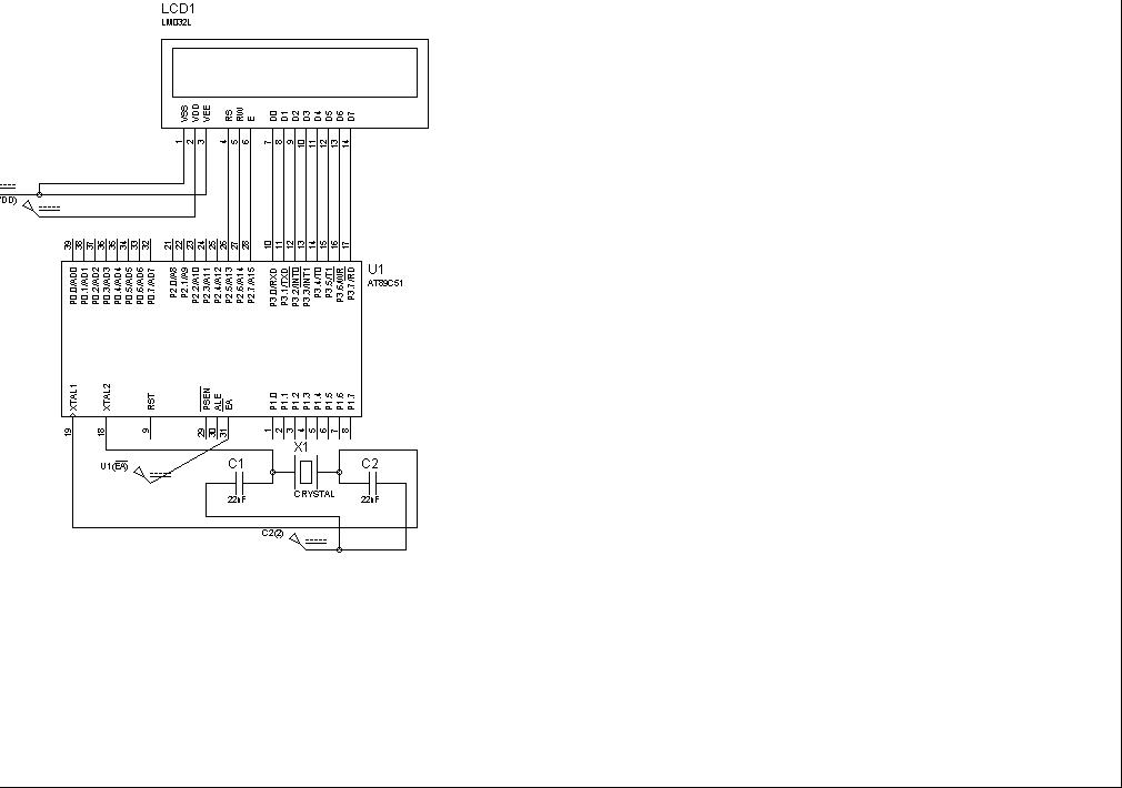
CODE WAS TRIED ON PROTEUS...THE DESIGN IS


this is the working code for 89s52. You didnt initialize your ports in the code

ORG 0000H
JMP MAIN
MAIN:
MOV P1,0 // Data Pins of LCD
CLR P2.0 //RS
CLR P2.1 // WR
CLR P2.2 // Enable
ACALL DELAY
ACALL DELAY
MOV A,#0x38
ACALL COMWRT
ACALL DELAY
MOV A,#0x0C
ACALL COMWRT
ACALL DELAY
MOV A,#0x01
ACALL COMWRT
ACALL DELAY
MOV A,#0x85
ACALL COMWRT
ACALL DELAY
MOV A,#'A'
ACALL DATWRT
MOV A,#'B'
ACALL DATWRT
MOV A,#'C'
ACALL DATWRT
MOV A,#'D'
ACALL DATWRT
MOV A,#'E'
ACALL DATWRT
ACALL DELAY
ACALL DELAY

S5:JMP S5

COMWRT:
MOV P1, A
CLR P2.0
CLR P2.1
SETB P2.2
ACALL DELAY
CLR P2.2
RET

DATWRT:
MOV P1,A
SETB P2.0
CLR P2.1
SETB P2.2
ACALL DELAY
CLR P2.2
RET

DELAY:
MOV R5,#50

WAIT0:
MOV R6,#50

WAIT1:
MOV R7,#100

WAIT2:
DJNZ R7,WAIT2
DJNZ R6,WAIT1
DJNZ R5,WAIT0
RET

END
 
Use terminal mode and use power and ground for 5v and GND respectively. Is your simulation successful?
 

Also see whether common point of C1 and C2 is connected to proper ground.
 

sir
my simulation did not showed any thing.....
what is terminal mode......:???:

---------- Post added at 00:32 ---------- Previous post was at 00:32 ----------

my new code...

org 000h
;===========================
checkled EQU p1.0
checkled2 EQU p1.5
RS EQU p2.0
RW EQU P2.1
EN EQU P2.2

jmp start
;===========================
start:
;===========================
setb checkled ;CHECK THE LED START LED
acall delay


acall INITIALISATION
ACALL WRITE_DATA


clr checkled
acall delay
jmp start_2

START_2:
setb checkled2
acall delay
clr checkled2
acall delay
jmp start_2


;===========================
INITIALISATION:
;===========================
ACALL delay_8US
;MOV A,#00H
;ACALL INIT_LCD
MOV A,#38H
ACALL INIT_LCD
MOV A,#0EH
ACALL INIT_LCD
MOV A,#01H
ACALL INIT_LCD
MOV A,#06H
ACALL INIT_LCD
;===========================
CHECKBUSY:
;===========================
SETB P3.7
CLR RS
SETB RW
AGAIN:
SETB EN
CLR EN
JB P3.7,AGAIN

RET
;===========================
init_lcd:
;===========================
ACALL CHECKBUSY
CLR RS
CLR RW
SETB EN
MOV P3,A
CLR EN
ret
;===========================
WRITE_DATA:
;===========================
MOV A,#'A'
ACALL DATAROUTINE

MOV A,#'A'
ACALL DATAROUTINE

MOV A,#'A'
ACALL DATAROUTINE

MOV A,#'A'
ACALL DATAROUTINE

RET
;===========================
DATAROUTINE:
;===========================
ACALL CHECKBUSY

SETB RS
CLR RW
SETB EN
MOV P3,A
CLR EN
ACALL CHECKBUSY
RET
;===========================
delay:
;===========================
mov r6,#5
d1:
mov r7,#100
d2:
mov r5,#250
djnz r5,$
djnz r7,d2
djnz r6,d1
ret
;===========================
;===========================
delay_8US:
;===========================
NOP
NOP
NOP
NOP
NOP
NOP
NOP
NOP
RET
;===========================

end

---------- Post added at 00:34 ---------- Previous post was at 00:32 ----------

please check the coding

i am not sure my coding is well or my simulated hardware.....

---------- Post added at 00:40 ---------- Previous post was at 00:34 ----------

sir

u told me i did not initialised my ports ....."initialising means sending clear to port" and why is it necessary to initialise the ports arent they by default at 0v
 

When your 89c51 power up all your ports becomes input (Logic 1). To use them for lcd interfacing you have to make them as output(Logic 0).
Terminal Mode is present in the left pane of ISIS. you have to use proper ground and vcc in your circuit in proteus.for this you have to use POWER and GROUND present in Terminal Mode.
your code has errors. Lcd require sometime to execute instructions as it has built in controller. after every command you have to give delay from(100ms to 200ms).

try to use my code its is working one
 

MOV P1,0 // Data Pins of LCD

at the start you wrote

mov p1,0

why did not you wrote

mov p1,#0


whats the difference between the two

---------- Post added at 21:49 ---------- Previous post was at 21:13 ----------

why u finished with endless loop

s5:
jmp s5
 
Last edited:

MOV A,#32H means load that value to A. If you dont use # it means copy contents from memory location.

I should use MOV A,#00H

because my program was finished ,so to make my controller busy i made endless loop.
 

is it practically right to end with endless lop.......

i want to display these alphabet on real world .... should i copy the schematic on real world or some thing extra will be needed


It is better to make your microcontroller busy forever. You have to connect the reset circuitry with RST pin. Pin 20 of 89s51 should be ground and pin 40 should connect to VCC.
 

when i try the code with delays its working perfectly well but when i try to check lcd busy flag status its strucked ....why is that so ...

please help me...:???:

code to check busy status is

busylcd:
SETB P3.7
SETB RW
CLR RS
SETB EN
S5:
SETB EN
CLR EN
JB P3.7,S5
RET

:-?:-?:!::?::?:
 
Last edited:

I personally dont use BUsy Flag method, it usually create problems while implementing on hardware.
 

are you doing all on proteus or you also did it practically on vero board or bread board? if not then i think your LCD will not respond any thing as i see your schemetic.
 

i am doing on proteus .... can you suggest me simulation software which is more close to practical world.......

So that i just have to transform my simulated design .....

So that i can avoid hidden complexities
 

For controller based projects Proteus is best for simulation and that is the reason why proteus is very popular among hobbyists and engineers. Is your hardware working now?
 

yes.... i have designed a small gadget with connectors at the port ....

that gadget was working with my simple led code which i placed on bread board..... but lcd code is not working
 

Status
Not open for further replies.

Similar threads

Part and Inventory Search

Welcome to EDABoard.com

Sponsor

Back
Top