Continue to Site

Welcome to EDAboard.com

Welcome to our site! EDAboard.com is an international Electronics Discussion Forum focused on EDA software, circuits, schematics, books, theory, papers, asic, pld, 8051, DSP, Network, RF, Analog Design, PCB, Service Manuals... and a whole lot more! To participate you need to register. Registration is free. Click here to register now.

LCD interface issue with PIC16F877A

Status
Not open for further replies.

Prince Vegeta

Member level 5
Joined
May 29, 2012
Messages
84
Helped
0
Reputation
0
Reaction score
0
Trophy points
1,286
Activity points
2,011
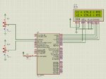
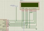
I connected the LCD as shown in the attachments.

and the C program of PIC16F877A have the following:

Code:
// LCD module connections
sbit LCD_RS at RB4_bit;
sbit LCD_EN at RB5_bit;
sbit LCD_D4 at RB0_bit;
sbit LCD_D5 at RB1_bit;
sbit LCD_D6 at RB2_bit;
sbit LCD_D7 at RB3_bit;

sbit LCD_RS_Direction at TRISB4_bit;
sbit LCD_EN_Direction at TRISB5_bit;
sbit LCD_D4_Direction at TRISB0_bit;
sbit LCD_D5_Direction at TRISB1_bit;
sbit LCD_D6_Direction at TRISB2_bit;
sbit LCD_D7_Direction at TRISB3_bit;
// End LCD module connections

// LCD text variables
char txt1[] = "V1 = ";
char txt2[] = "V2 = ";
char txt3[6] = "    ";
char txt4[6] = "    ";
char txt5[] = "V RMS";

The LCD gets launched and it's light is on, and there is some black things in the 1st row and I read it should be working like this.

BUT, the readings never get shown!

THEN, I tried the PIC without LCD and surprisingly it stopped working like before (it was working with other functions).

So, what do you suggest?
 

Attachments

  • lcd.JPG
    lcd.JPG
    105.3 KB · Views: 71

Is that all the code? can you post all of it please?
RB0 is interrupt pin, make sure u disable all interrupts or use a different pin.
 

Code:
float  v, v1, v2, v_peak;
unsigned int adc1, adc2;
unsigned char l_byte, h_byte;
char ch1[5], ch2[5];
float ADR, adc;
unsigned short channel;
unsigned short current_status, prev_status;

/////* Definitions */////

#define v_rms_min 200                          // lowest alloable RMS voltage
#define adc_rms_min 806                        // 220v

#define source_1  RD0_bit                      // source_1 @ pin RD0
#define source_2  RD1_bit                      // source_2 @ pin RD1
#define no_active_source  RD2_bit              // no_active_source indication LED @ pin RD2
#define source_1_on  RD3_bit                   // source_1_on indication LED @ pin RD3
#define source_2_on  RD4_bit                   // source_2_on indication LED @ pin RD4


// LCD module connections
sbit LCD_RS at RB4_bit;
sbit LCD_EN at RB5_bit;
sbit LCD_D4 at RB0_bit;
sbit LCD_D5 at RB1_bit;
sbit LCD_D6 at RB2_bit;
sbit LCD_D7 at RB3_bit;

sbit LCD_RS_Direction at TRISB4_bit;
sbit LCD_EN_Direction at TRISB5_bit;
sbit LCD_D4_Direction at TRISB0_bit;
sbit LCD_D5_Direction at TRISB1_bit;
sbit LCD_D6_Direction at TRISB2_bit;
sbit LCD_D7_Direction at TRISB3_bit;
// End LCD module connections

// LCD text variables
char txt1[] = "V1 = ";
char txt2[] = "V2 = ";
char txt3[6] = "    ";
char txt4[6] = "    ";
char txt5[] = "V RMS";


unsigned int ADCRead(unsigned short channel){

        if (channel == 0) {ADCON0 = 0x81;}          // convert from channel0
        if (channel == 1) {ADCON0 = 0x89;}          // convert from channel1

        delay_us(80);                               // Acquisition Delay
        GO_DONE_bit = 1;                            // Set GO_DONE bit to start conversion
        while (GO_DONE_bit == 1);                   // Wait for bit to be cleared
                                                    // If bit is cleared, this means conversion is over
        l_byte = ADRESL;
        h_byte = ADRESH;
        ADR = (h_byte<<8)|l_byte;
        return ADR;
}

float RMS_calculator (unsigned short source) {

                channel = source;
                adc = ADCRead(channel);
                v_peak = (adc*396)/1023;

                v = v_peak/sqrt(2);                      // rms value for sinewaves

               return v;
}

unsigned short check_status() {
            /*
         if ( adc1 <= adc_rms_min ) {

            if ( adc2 >= adc_rms_min )
              { current_status = 2; }
            else { current_status = 3; }
         }
         else { current_status = 1; }
              */
                  if ( v1 <= v_rms_min ) {

                   if ( v2 <= v_rms_min ) { current_status = 3; }
                   else { current_status = 2; }
            }
         else { current_status = 1; }

            return current_status;
         }
         

void apply_status() {

        switch ( current_status )   {
        
        case 1:
               {
               source_2 = 0;                             // deactivate source_2
               delay_ms(10);                              // wait 5ms
               source_1 = 1;                             // activate source_1
               source_2_on = 0;                          // source_2_on LED is OFF
               source_1_on = 1;                          // source_1_on LED is ON
               no_active_source = 0;                     // no_active_source LED is OFF
               break;
               }

        case 2:
               {
                source_1 = 0;                             // deactivate source_1
                delay_ms(10);                              // wait 5ms
                source_2 = 1;                             // activate source_2
                source_1_on = 0;                          // source_1_on LED is OFF
                source_2_on = 1;                          // source_2_on LED is ON
                no_active_source = 0;                     // no_active_source LED is OFF
                break;
                }
                
        case 3:
               {
                source_1 = 0;                               // source_1 off
                source_2 = 0;                               // source_2 off
                no_active_source = 1;                       // no_active_source LED is ON
                source_1_on = 0;                            // source_1_on LED is OFF
                source_2_on = 0;                            // source_2_on LED is OFF
                break;
                }
      }


}

void main() {


        CMCON = 7; //Disable comparator

        PORTA = 0;
        TRISA = 0xff;

        PORTD = 0;
        TRISD = 0;

        PORTC = 0;
        TRISC = 0;

        PORTB = 0;
        TRISB = 0;

        ADCON0 = 0x81;
        ADCON1 = 0xC0;                            // all portA pins are analog   // was 0xCE

        source_1 = 0;                             // source_1 off
        source_2 = 0;                             // source_2 off
        source_1_on = 0;                          // source_1_on LED is OFF
        source_2_on = 0;                          // source_2_on LED is OFF
        no_active_source = 1;                     // no_active_source LED is OFF
        v1 = 0;
        v2 = 0;
        adc1 = 0;
        adc2 = 0;
        current_status = 3;
        apply_status();
        
        /// LCD initialization ///
        
        Lcd_Init();                        // Initialize LCD
        Lcd_Cmd(_LCD_CLEAR);               // Clear display
        Lcd_Cmd(_LCD_CURSOR_OFF);          // Cursor off
        Lcd_Out(1,1,txt1);                 // Write text in first row
        Lcd_Out(2,1,txt2);                 // Write text in second row


      // option_reg=0b00101111;
while (1){
         prev_status = current_status;
        // calculate channel0 voltage

        v1 = RMS_calculator (0);
        //adc1 = ADR;


                             // calculate channel1 voltage
        v2 = RMS_calculator (1);
       // adc2 = ADR;


        current_status = check_status();
        if ( current_status != prev_status ) { apply_status(); }
        delay_ms(100);

       // display v1
       floattostr(v1,ch1);
       txt3[0] = ch1[0];
       txt3[1] = ch1[1];
       txt3[2] = ch1[2];
       txt3[3] = ch1[3];
       txt3[4] = ch1[4];
       
       Lcd_Out(1,6,txt3);
       Lcd_Out(1,12,txt5);


       // display v2
       floattostr(v2,ch2);
       txt4[0] = ch2[0];
       txt4[1] = ch2[1];
       txt4[2] = ch2[2];
       txt4[3] = ch2[3];
       txt4[4] = ch2[4];

       Lcd_Out(2,6,txt4);
       Lcd_Out(2,12,txt5);
       

  }
}

here is the full code.
 

Where is the oscillator setting? Where are the configuration bits? If that's your entire program it likely does not work at all. What does the circuit look like?...Is the crystal or resonator hooked up properly? Are the right pins connected to the power rails?
 

Where is the oscillator setting? Where are the configuration bits? If that's your entire program it likely does not work at all. What does the circuit look like?...Is the crystal or resonator hooked up properly? Are the right pins connected to the power rails?

yes i connected it properly, I am using 20MHz crystal.

I didn't touch any config bits, fuses, osc settings (I followed the data sheet and made it on external crystal). tell me how can I do these things plz.

the circuit is an automatic transfer switch... PIC will read 2 voltage sources and activate only one of them according to some simple conditions.

RD0 and RD1 bits are those output triggering pins which will activate MOC3092 Triac driver which, in turns, drive a TRIAC that is connected to the load and the source.

I tried this circuit and it used to work before, just before I hooked up the LCD. after that the 2 outputs didn't output anything anymore.
 

**broken link removed**
Follow this link.

This may help you.

Best wishes :)
 
Last edited by a moderator:

It is working.

**broken link removed**
 

Attachments

  • adcrms.jpg
    adcrms.jpg
    228.7 KB · Views: 101
  • lcd_pic16f877a.rar
    94.2 KB · Views: 41
Last edited by a moderator:

I know it's working in Proteus but in real-world LCD stuff isn't.

what is the file you attached?

sbit LCD_D4 at RB0_bit;

Try using another output instead of RB0 or see here how to disable interupts.
**broken link removed**

I put this line: INTE_bit = 0; but RB0/INT interrupt is disabled by default and no need of this.

BTW, someone told me to check configuration bits and fuse settings which I didn't touch... is there what should be done?

jayanth.devarayanadurga

because you have the software now, can you try it in real world and tell me the result?
 
Last edited by a moderator:

XT (xtal) works fine up to 4MHz.
HS (High Speed) in needed for freq > 4MHz

You have to set the clock according to your crystal speed.
 

does your LCD have BUSY FLAG?
have you checked for it?
many LCDs have such BUSY bit.
this bit shows that LCD is processing your previous command and you must have to wait for this bit get cleared itself, before sending another command.

if you are using mikroe, thay should have taken care about this.
 

sorry, i reverted back to HS. my crystal is 20mhz but I changed the setting which was 8mhz in project settings.

___

I don't know about BUSY FLAG thing... can you tell me more about it?

my LCD is 1602a v1.2
 

once i made this code for my trainees.... its for at89c52 ... keil...
it has lcd routines. there is busy bit implementation too..
go through it..

- - - Updated - - -

BUSY bit is set on MSB of the data port by the lcd, when it is processing on previouse command .
until it clears this bit it will not accept any commands further,
we have to poll for this FLAG bit in our code.

but if you are using mikro e compilers, they should have taken care about this flag in their library.
or they have separate library function for it?
p.s. i do not use mikroe , other wise i would have tell you the exact function, if there is any.

you can convert my keil code to drive your lcd. it does not use library function (as keil don't have any), but only 3 simple functions.
 

Attachments

  • 0.zip
    45.9 KB · Views: 46
Last edited by a moderator:

Status
Not open for further replies.

Similar threads

Part and Inventory Search

Welcome to EDABoard.com

Sponsor

Back
Top