Continue to Site

Welcome to EDAboard.com

Welcome to our site! EDAboard.com is an international Electronics Discussion Forum focused on EDA software, circuits, schematics, books, theory, papers, asic, pld, 8051, DSP, Network, RF, Analog Design, PCB, Service Manuals... and a whole lot more! To participate you need to register. Registration is free. Click here to register now.

LCD and interrupt functions doubt in 16f887 micro controller

Status
Not open for further replies.

ahshiq

Newbie level 4
Joined
Aug 27, 2015
Messages
6
Helped
0
Reputation
0
Reaction score
0
Trophy points
1
Activity points
58
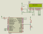
initially "hello" message displays at 0x80. if i press a respective key "hello" should disappears another msg "wait" shoud display at 0x80. then if i press another key "wait" should disappear again "hello" should come. how could be written in interrupt function
 

HI-TECH complier
 

Show your circuit. If you have Proteus, post the Proteus file. I need to know which pins are used for buttons and LCD to write a code for you.
 

no sir i dont have proteus. this is my code


Code C - [expand]
1
2
3
4
5
6
7
8
9
10
11
12
13
14
15
16
17
18
19
20
21
22
23
24
25
26
27
28
29
30
31
32
33
34
35
36
37
38
39
40
41
42
43
44
45
46
47
48
49
50
51
52
53
54
55
56
57
58
59
60
61
62
63
64
65
66
67
68
69
70
71
72
73
74
75
76
77
78
79
80
81
82
83
84
85
86
87
88
89
90
91
92
93
94
95
96
97
98
99
100
101
102
103
104
105
106
107
108
109
110
111
112
113
114
115
#include<htc.h>
#define rs_pin RC0
#define rw_pin RC1
#define e_pin RC2
 
static void interrupt isr();
void data(unsigned char);       //to display data in lcd
void commd(unsigned char);      //torun lcd comand
void lcd_init(void);            //to initialise lcd
void delayms(unsigned int);     //to create display
void welcome(void);
void coin(void);
 
unsigned char msg[]={"welcome"};
unsigned char msg1[]={"insert coin"};
unsigned char i;
 
void main()
{
    OSCCON=0x75;
    OPTION=0X07;        /* to select 1:256 */
    T0IE=1;             // TO ENABLE INTERRUPT                  
    T0IF=0;             // TO SET FLAG 
    TMR0=0XB2;          /* TIMER CALCULATION  FOR 1 SEC DELAY FROM WHERE 
                        TO START i.e BIT 178 TO FF B2 IS 10ms */
    GIE=1;
 
    TRISC=0X00;
    TRISB=0X00;
    PORTC=0X00;
    PORTB=0X00;
    TRISD=0xFF;
    PORTD=0xFF;
    delayms(50);
    lcd_init();
        delayms(500);   
    welcome();
    while(1)
    {


    }
}
 
void lcd_init(void)
{
    commd(0x38);    //8bit mode /2 line /5*7 dots- per char
    commd(0x06);    //auto increment of cursor position
    commd(0x0E);    //disp on
    commd(0x01);    //clear display
}
 
void data(unsigned char lcd_data)
{
    PORTB=lcd_data; //place data in portd
    rs_pin=1;       //make reset pin high
    rw_pin=0;       //make reset pin low
    e_pin=1;        //make enable pin high
    delayms(10);
    e_pin=0;        //make enable pin low
}
 
void commd(unsigned char commd)
{
    PORTB=commd;    //place data in portd
    rs_pin=0;       //make reset pin high
    rw_pin=0;       //make reset pin low
    e_pin=1;        //make enable pin high
    delayms(10);
    e_pin=0;        //make enable pin low
}
 
void delayms(unsigned int xx)
{
    unsigned int j,k;
    for(j=0;j<xx;j++)
    for(k=0;k<10;k++);
}
void welcome(void)
{
    commd(0x80);            //move cursor to first line
        for(i=0;i<7;i++)
        {
            data(msg[i]);       //display msg array content in line 1
        }
    commd(0x1c);
    delayms(1000);
    
}
static void interrupt isr()
    {
        if(T0IF==1)
            {
                    T0IF=0;
                    if(RD0==1)
                    {
                    
                    coin();
                    while(RD0==1);
                    }
                    
                //  TMR0=0XB2;
                //  ms++;
            }
    }
void coin(void)
{
    delayms(500);
        commd(0xc0);            //move cursor to second line
        for(i=0;i<11;i++)
        {
            data(msg1[i]);
        }
}

 
Last edited by a moderator:

I can see one problem straight away - you are held in the ISR until RD0 is released. That will block any other interrupts from being serviced. You also call another function 'coin()' from inside the ISR and it contains a delay. Best to set a variable when the ISR is entered, clear the interrupt then leave. You can check that variable in the main() part of your code without disrupting the interrupts. At the moment your timer may be very inaccurate and inconsistent depending on the state of RD0.

Brian.
 

sir please explain how to set a variable in interrupt. ex"coin"has to display has to display when i give input to RD0. if i release RD0 old msg previous "welcome" has to show. that is i have to clear the interrupt.
 

Why do you want to use Timer0 ? See my attached codes. One displays "Welcome" message. The rev1 version displays two messages "Welcome" and "Insert Coin" when button is pressed. Your circuit should be as shown in the image. I have also included Proteus 8.2 SP2 format file. If you want to use interrupt to detect button press then you have to use RB0/INT0 pin. If you can use RB0 pin for button then I will give you a code which uses it to detect button press using INT0 interrupt. I have used 4 bit LCD code. RW pin of LCD can be connected to ground or if you have it connected to RC1 then it is also ok because in code I have set 0 to RC1. D0 to D3 pins of LCD can be left floating.

I have used MPLAB 8.92 and Hi-Tech PICC 9.83. I have set config bits in IDE. If you want MPLAB X code then let me know and I will make MPLAB X version of project.

I have compiled the code for 4 MHz XT Oscillator. MCLR is enabled and pulled high using a 10k resistor, Circuit doesn't show crystal and associated 27pf capacitors. You have to add them.

broken link removed

- - - Updated - - -

Edit:

Try the rev2 file. See simulation video (.avi) file inside. It works as you want but the code execution will be blocked when it encounters the while(condition) loops. A better code can be written using INT0 interrupt.

- - - Updated - - -

This is a version which uses INT0 pin for the button. It doesn't have any blocking code.
 

Attachments

  • Switch and LCD.rar
    124.7 KB · Views: 87
  • Switch and LCD rev1.rar
    126.9 KB · Views: 80
  • Switch and LCD.png
    Switch and LCD.png
    38.6 KB · Views: 105
  • Switch and LCD rev2.rar
    250.4 KB · Views: 78
  • Switch and LCD Using INT0.rar
    290.2 KB · Views: 74
  • schematic.png
    schematic.png
    38.1 KB · Views: 96
Last edited by a moderator:

Status
Not open for further replies.

Similar threads

Part and Inventory Search

Welcome to EDABoard.com

Sponsor

Back
Top