Continue to Site

Welcome to EDAboard.com

Welcome to our site! EDAboard.com is an international Electronics Discussion Forum focused on EDA software, circuits, schematics, books, theory, papers, asic, pld, 8051, DSP, Network, RF, Analog Design, PCB, Service Manuals... and a whole lot more! To participate you need to register. Registration is free. Click here to register now.

[PIC] LCD(16x4) Interfacing Problem with PIC18F4550

Status
Not open for further replies.

SAMO6

Newbie level 5
Joined
Nov 14, 2016
Messages
10
Helped
0
Reputation
0
Reaction score
0
Trophy points
1
Activity points
139
Hello Everyone,

I am trying to interface 16x4 LCD with PIC18F4550.The simulation in proteus is working fine.But,I am not able to display any characters on LCD (Hardware).
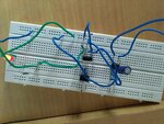
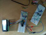
I am getting only Black boxes on LCD screen, and one more thing only two lines are showing black boxes.Other two lines are showing nothing.Please find the attached images, So that you will understand my problem well.
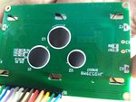
I am using 16x4 LCD JHD539M8. I searched a lot for datasheet of this LCD.If you have datasheet of this LCD, then please send it to me.
I am using:
PIC18F4550,20Mhz Crystal Oscillator, LCD is interfaced using 8 bit mode.


Code C - [expand]
1
2
3
4
5
6
7
8
9
10
11
12
13
14
15
16
17
18
19
20
21
22
23
24
25
26
27
28
29
30
31
32
33
34
35
36
37
38
39
40
41
42
43
44
45
46
47
48
49
50
51
52
53
54
55
56
57
58
59
60
61
62
63
64
65
66
67
68
69
70
71
72
#include<P18F4550.h>
#define RS PORTCbits.RC0
#define En PORTCbits.RC1
// LCD functions
void delay(unsigned int itime)
{
    unsigned int i,j;
    for(i=0;i<itime;i++)
        for(j=0;j<165;j++);
}
// LCD Functions
void lcdcmd(unsigned char value)
{
    PORTB=value;
    RS=0;   //Select command register
   // delay();
    En=1;           // High to Low pulse on Enable pin of LCD
    delay(250);
    En=0;
}
void lcddata(unsigned char value)
{
    PORTB=value;
    RS=1;//Select data register
   // delay();
    En=1;           // High to Low pulse on Enable pin of LCD
   delay(250);
    En=0;
 
}
 
 
void lcdinit()
{
     lcdcmd(0x38);  //Call Command subroutine (value=0x38)
  delay(250);
    lcdcmd(0x0E);
  delay(250);
    lcdcmd(0x01);
    //delay();
   // lcdcmd(0x06);
   // delay();
 
}
 
void stringlcd(const char * s)
{
            while(*s)
            lcddata(*s++);
}
void main()
{
    TRISB = 0x00;                           //Configure Data bus
 
    TRISCbits.TRISC0 = 0;                   // Configure RC0 as RS
    TRISCbits.TRISC1 = 0;                   // Configure RC1 as EN
 
    lcdinit();
    delay(250);
    lcdcmd(0x80);
    delay(250);
    stringlcd("Hello World");
    delay(250);
    lcdcmd(0xC0);
    delay(250);
    stringlcd("Good Morning");
    lcdcmd(0x90);
    stringlcd("SAMO");
    lcdcmd(0xD0);
    stringlcd("Systems");
    
}


I tried a lot. I also tried pull up resistors of 10K.But, still nothing is working.
Please help.
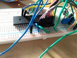
I have attached my code,proteus simulation model picture, hardware pictures with this post.
Thank you. IMG_20170416_160858.jpgIMG_20170416_160906.jpgIMG_20170416_160914.jpgIMG_20170416_161055.jpgIMG_20170416_161123.jpgIMG_20170416_173252.jpg
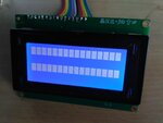
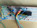
 
Last edited by a moderator:

For PIC18F devices you should use LATx registers for output ports.
 

Thanks for replying to my query.
But, when I tested simple LED blinking program on the same breadboard, one thing I found in my breadboard circuit is that there is some problem with crystal,Because, when I touched that crystal, LED started blinking and as soon as I released that crystal, LED stopped blinking, and when it stopped it was either in ON state(Glowing,that is not blinking) or in OFF state.
So, I think there might be some problem with crystal. But, I tried different crystals as well and also tried circuit with crystal mounted on zero pcb to detect if there is any issue with breadboard or not.
But,in zero pcb case also, I required to press or touch the crystal to make LED start blinking.

Though,This post might not be relevant to this LCD thread but, I think, I need to solve this to get things running.

So, Please suggest me on this problem.If you know any solution regarding this,please tell me.
 

I don't know about crystal problem. If you are using 20MHz crystal then it might not work properly on breadboard.
 

hello,

You are using long wire with your breadboards... and no capacitors accross power supply lines ( green and blue wiring)
so add 100nF accross 100µF , next to the MCU power supply rails..

what is the VCC voltage value ?
what configuration bits ?
what are the 2 capacitors values beside Quartz pins ?

i tested many prototype application on breadbord without Problem with a 20MHz quartz .. even it is not recommended.
 
  • Like
Reactions: SAMO6

    SAMO6

    Points: 2
    Helpful Answer Positive Rating
Input supply: Vdd=5V, Input current=18mA. Is it ok?

Configuration bits:
MCLR=Enable
FOSC=HS
BOR=ON
LVP=OFF
ICPRT=OFF

Capacitors beside Quartz crystal are of 20pF.
 

That display is typical of when the LCD is powered on but not initialised. Timing is critical in initialising these devices and I suggest that you don't use your own 'delay' function - the compiler will almost certainty provide one and you should use that. Better still, use a timer.
Of course, any delay function will require that the oscillator is working correctly and we can't see anything about how you have set that up.
Also, Okada is correct that you should use the LAT registers and not the PORT as you could well be experiencing the RMW problem and that will also prevent the initialisation from completing.
And that initialisation function seems to be much too short but I don't have the documentation in front of me.
Susan
 
  • Like
Reactions: SAMO6

    SAMO6

    Points: 2
    Helpful Answer Positive Rating
Status
Not open for further replies.

Similar threads

Part and Inventory Search

Welcome to EDABoard.com

Sponsor

Back
Top