Continue to Site

Welcome to EDAboard.com

Welcome to our site! EDAboard.com is an international Electronics Discussion Forum focused on EDA software, circuits, schematics, books, theory, papers, asic, pld, 8051, DSP, Network, RF, Analog Design, PCB, Service Manuals... and a whole lot more! To participate you need to register. Registration is free. Click here to register now.

LCD 12864B V2.0

Status
Not open for further replies.

HighTechPower

Member level 5
Joined
Jul 10, 2020
Messages
91
Helped
0
Reputation
0
Reaction score
0
Trophy points
6
Activity points
703
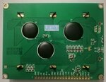
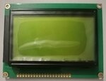
Hi. I'm using graphical LCD and on it's PCB it's written as "12864B V2.0". The printed pin outs are as below,
1)GND
2)VCC
3)VO
4)RS
5)R/W
6)E
7)DB0
8)DB1
9)DB2
10)DB3
11)DB4
12)DB5
13)DB6
14)DB7
15)PSB
16)NC
17)RST
18)VOUT
19)BLA
20)BLK

The issue is I see a lot of source code for another 12864 LCD known as GLCD. The only difference is pin 15 is CS1 and pin 16 is CS2 on that. Can I use that same code on my LCD, if not, can you show me some link for source code relevant to my LCD as I could not find out.
 

Said 12864B V2.0 uses apparently Sitronix 7920 controller, a display with two CS lines surely a completely different chip. You should be able to find ST7920 code, there are still setup parameters specific for the LCD glass that might need adjustment.

"12864" just refers to 128 x 64 dot graphic display.
 
Also to note there is a variable resistor at the back of PCB. What is it's purpose here?
 

Hi,

why don´t you show photos?

Then we can see: position, size, value, pcb marking, wiring....

Klaus
 

Also to note there is a variable resistor at the back of PCB. What is it's purpose here?
You are asking because you don't have a useable datasheet of the LCD module? Apparently there's none, I see endless forum discussions how to deal with the internal VR1 poti, how it's related to external V0 pin, what's the necessary supply voltage to get accepatble contrast etc. If there's actually no datasheet available: hands off!
 

Hi,

why don´t you show photos?

Then we can see: position, size, value, pcb marking, wiring....

Klaus

Plz attached here find the pics of LCD.
 

Attachments

  • High Tech Power LCD Back.jpg
    High Tech Power LCD Back.jpg
    1.3 MB · Views: 759
  • High Tech Power LCD Front.jpg
    High Tech Power LCD Front.jpg
    1.1 MB · Views: 275

Hi,

From the traces ... it seems the pot is connected to VO.
Use a DVM with continuity check ... while the whole display is not connected at all.

My idea:
* in your case the pot is installed thus you don´t need to connect VO.
* (there may be displays without pot installed, then you need to connect VO for proper contrast operation)
Don´t connect VO while the pot is installed. You may immediately destroy the pot.

Klaus
 

Hello,

i have a similar LCD , **broken link removed**
i can display some texte , but was not able to use graphics fonctions
it is a bit complicated to use it , and has a big current (mA) comsumption ,
so not recommended for new project. ILLI9341 is better...
 

Status
Not open for further replies.

Similar threads

Part and Inventory Search

Welcome to EDABoard.com

Sponsor

Back
Top